Author: chamal

  • Plant Safety: A Foundation for Chemical Plant Safety Excellence

    Plant Safety: A Foundation for Chemical Plant Safety Excellence

    In the chemical processing industry, safety is not just a regulatory requirement—it’s a lifeline. Chemical plants deal with hazardous substances, high pressures, extreme temperatures, and reactive systems that can pose serious threats if not managed properly. A single lapse can lead to catastrophic consequences, affecting people, the environment, and business sustainability.

    This guide offers a comprehensive learning structure and explains the critical safety systems, hazards, tools, and best practices every chemical engineer, technician, or plant operator should know.


    Learning Structure for Plant Safety

    To build a strong safety culture, you need a structured educational approach. Below is a framework that guides safety training and competency development in chemical industries.


    1. Introduction to Plant Safety

    • Why Safety Matters:
      Safety is the foundation of sustainable operations. It prevents accidents, protects employees, preserves assets, and enhances plant efficiency.

    • Basic Safety Terminology:
      Terms like hazard, risk, near-miss, incident, exposure, and mitigation must be well understood to foster clear communication.

    Hazard – A potential source of harm or danger.
    Example: A flammable liquid stored near a heat source.

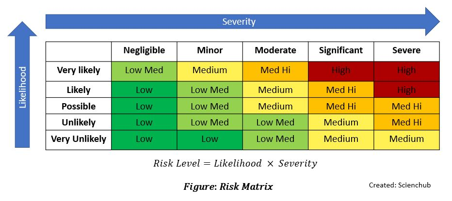
    Risk – The chance that a hazard will cause harm, considering the likelihood and severity.
    Example: The risk of fire increases if the flammable liquid is not stored properly.

    Near-Miss – An unplanned event that did not cause harm but had the potential to do so.
    Example: A worker slips but regains balance and avoids a fall.

    Incident – An event that causes or could cause harm, injury, damage, or loss.
    Example: A chemical spill that causes skin burns or equipment damage.

    Exposure – The contact or presence of a person with a hazard (chemical, physical, or biological).
    Example: Inhaling solvent vapors or touching a hot surface.

    Mitigation – Actions taken to reduce the severity or impact of a hazard or incident.
    Example: Installing gas detectors and emergency shutdown systems.

    • Types of Hazards:


    2. Hazard Identification and Risk Assessment

    • Methods of Hazard Identification:
      Use checklists, job safety analysis (JSA), audits, and inspections to detect hazards before they cause harm.

    • Risk Assessment Process:
      Evaluate likelihood × severity to prioritize controls.

    • Hierarchy of Controls:

    1. Elimination

    Remove the hazard entirely from the workplace.
    Example: Replace a toxic chemical process with a safer method.

    2. Substitution

    Replace the hazard with a less dangerous one.
    Example: Use a less volatile solvent.

    3. Engineering Controls

    Physically isolate people from the hazard.
    Example: Enclose equipment, install ventilation or interlocks.

    4. Administrative Controls

    Change how people work to reduce exposure.
    Example: Training, shift rotations, signage, SOPs.

    5. Personal Protective Equipment (PPE)

    Last line of defense—protect the worker.
    Example: Gloves, goggles, respirators.


    3. Safety Policies, Procedures, and Standards

    • Developing Policies:
      Establish clear goals, responsibilities, and enforcement mechanisms.

    • Roles and Responsibilities:

      • Management: Resource allocation and accountability

      • Supervisors: Daily oversight and team training

      • Employees: Safe conduct, reporting, and cooperation

    • Safety Management Systems (SMS):
      Frameworks like ISO 45001 integrate safety into daily operations.

    • Legal Compliance:
      Adhere to OSHA, EPA, and local regulations to avoid fines and improve risk control.


    4. Personal Protective Equipment (PPE)

    PPE is vital for individual protection when other controls cannot eliminate risks.

    • Types of PPE:

    • Selection and Use:
      Based on hazard type and job requirement. Must be inspected regularly and fitted correctly.

    • Limitations:
      PPE does not eliminate hazards, only shields workers.


    5. Machine and Equipment Safety

    • Guarding & Interlocks:
      Protect operators from moving parts and accidental contact.

    • Lockout/Tagout (LOTO):
      Ensures complete isolation of energy sources during maintenance.

    • Standard Operating Procedures (SOPs):
      Documented safe practices for routine and emergency operations.

    • Inspection & Maintenance:
      Preventive upkeep of machinery avoids mechanical failures and unexpected downtime.


    6. Chemical Safety

    • Material Safety Data Sheets (MSDS / SDS):
      Provide information on handling, exposure, first aid, storage, and reactivity.

    • Safe Handling and Storage:
      Segregate incompatible chemicals, use proper containers, and label everything clearly.

    • Spill Control:
      Include containment trays, spill kits, and trained response teams.

    • Hazard Communication:
      Use signage, labels, and visual cues throughout the plant.


    7. Emergency Preparedness and Response

    • Types of Emergencies:
      Fire, explosion, chemical leaks, toxic gas release, medical emergencies

    • Emergency Action Plans (EAP):
      Step-by-step plans for evacuation, containment, and communication

    • Evacuation Routes & Muster Points:
      Clearly marked and regularly drilled

    • Firefighting Systems:
      Extinguishers, fire blankets, deluge systems, hydrants

    • First Aid:
      CPR-trained staff, stocked first-aid kits, and emergency eyewash stations


    8. Safety Training and Competency

    • Needs Assessment:
      Identify gaps based on job roles and site risks.

    • Training Delivery:
      Blended learning with classroom, online, and on-the-job methods

    • Safety Culture:
      Promote accountability, communication, and proactive behavior.

    • Competency Testing:
      Verify understanding through assessments, certifications, or simulations.


    9. Environmental Safety and Health

    • Waste Management:
      Segregation, treatment, and disposal of hazardous and non-hazardous waste

    • Pollution Prevention:
      Emission control, water conservation, solvent recovery

    • Health Hazards:
      Address noise, vibration, temperature, confined space entry

    • Ergonomics:
      Design tasks to minimize repetitive stress and fatigue


    10. Incident Reporting and Investigation

    • Reporting Procedures:
      Encourage prompt reporting of incidents and near misses

    • Root Cause Analysis (RCA):
      Use 5 Whys, Fishbone Diagrams to uncover systemic causes


    • Corrective/Preventive Actions (CAPA):
      Implement changes and monitor results

    • Performance Metrics:
      Track KPIs like TRIR, LTIR, near miss frequency


    11. Continuous Improvement in Safety

    • Audits & Inspections:
      Conduct regular reviews of systems and equipment

    • Safety Committees:
      Engage employees in identifying problems and solutions

    • Feedback Loops:
      Listen to workers—they often spot issues early

    • Use of Technology:
      Drones for inspection, SCADA systems, AI monitoring


    Why Safety Is Essential in Chemical Plants

    Without robust safety protocols, chemical plants can face:

    • Fires and Explosions

    • Toxic Releases

    • Operational Downtime

    • Injuries or Fatalities

    • Environmental Damage

    • Reputational and Legal Consequences

    These risks make safety not just ethical—but essential for business continuity.


    Common Hazards in the Chemical Industry

    • Flammable gases and liquids

    • Reactive chemicals

    • High pressure vessels

    • Toxic substances

    • Mechanical hazards from rotating or pressurized equipment

    • Ergonomic stress and fatigue

    • Electrical hazards and arc flashes


    Safety Tools and Systems in Chemical Plants

    Chemical plants are protected by multiple layers of safety systems, categorized as:

    1. Process Safety Systems

    • Pressure Relief Devices (PRDs): Prevent vessel ruptures

    • Emergency Shutdown Systems (ESDs): Automated equipment shutdown

    • Safety Instrumented Systems (SIS): Perform critical actions like closing valves or tripping pumps

    • Inert Gas Blanketing: Suppresses flammable vapor formation

    • Explosion Vents/Flame Arrestors: Release pressure and contain ignition

    2. Personal Protective Equipment (PPE)

    • Chemical suits, gloves, respirators, eye and face protection

    3. Gas and Fire Detection Systems

    • Fixed Detectors: For H₂S, CH₄, VOCs

    • Portable Monitors: For confined space entry

    • Smoke/Flame Detectors: Trigger suppression systems

    4. Fire and Explosion Protection Systems

    5. Control and Monitoring Systems

    • DCS (Distributed Control System): Manages process plant

    • PLC (Programmable Logic Controller): Controls specific units

    • SCADA: Supervises remote systems

    • Alarms: Alert deviations in pressure, temperature, flow, etc.

    6. Emergency Response and Escape Systems


    Best Practices for Safety in Chemical Plants

    • Conduct Process Hazard Analyses (PHA): HAZOP, What-If, Fault Tree

    • Follow Permit-to-Work Systems: Hot work, confined space, electrical

    • Standard Operating Procedures (SOPs): Well-documented and reviewed

    • Train Employees Regularly: Safety drills, PPE use, hazard awareness

    • Preventive Maintenance: Equipment, valves, sensors

    • Plan and Practice Emergencies: Evacuation, communication, firefighting


    Regulatory Compliance

    Plants must comply with:

    Compliance ensures legal operation and promotes industry best practices.


    Final Thoughts

    Safety in chemical plants is not optional—it is mission-critical. An effective safety strategy protects lives, prevents environmental disasters, enhances efficiency, and ensures long-term profitability.

    With well-structured learning, smart systems, and a proactive culture, zero incidents is not a dream—it’s an achievable standard.

    “You can’t manufacture safety—but you can engineer it into every step.”

  • Mass and Energy Balances: Core Concepts for Chemical Engineers

    Mass and Energy Balances: Core Concepts for Chemical Engineers

    In the world of chemical and process engineering, mass and energy balances are essential tools for designing, analyzing, and optimizing processes. Whether you’re sizing equipment, improving efficiency, or reducing environmental impact, a strong understanding of material and energy flows is critical.

    This guide breaks down the principles of mass and energy balances, how they are applied, and why they are fundamental to every chemical engineer’s toolkit.


    🔍 What Are Mass and Energy Balances?

    📌 Mass Balance (Material Balance)

    A mass balance is a quantitative account of all the material entering, leaving, accumulating, or being generated within a process unit. Based on the Law of Conservation of Mass, it ensures that:

    Input = Output + Accumulation – Consumption/Generation

    📌 Energy Balance

    An energy balance applies the First Law of Thermodynamics, which states that energy can neither be created nor destroyed. In a steady-state process (no accumulation):

    Energy In = Energy Out

    Energy balances include forms of energy such as:

    • Sensible heat

    • Latent heat

    • Work done (e.g., shaft work)

    • Chemical reaction energy


    🧮 General Mass Balance Equation

    Input+Generation=Output+Accumulation

    This equation applies to any material system and accounts for flow, chemical reactions, and storage.

    Special Cases:

    • Steady-State, Non-Reactive Systems:

    Input=Output

    No chemical reaction or accumulation occurs; mass simply flows through.

    • Steady-State, Reactive Systems:

      Input+Generation (by reaction)=Output

    Chemical reactions alter the mass flow by generating or consuming species, but there’s still no accumulation.


    General Energy Balance Equation

    Energy InEnergy Out=ΔEnergy Stored

    This is the first law of thermodynamics applied to a control volume.

    Components of Energy Inputs and Outputs:

    • Heat (Q) – energy transferred due to temperature difference

    • Work (W) – includes shaft work, electrical work, etc.

    • Enthalpy of material streams (H) – internal energy carried by flowing matter

    For Open Systems (e.g., continuous-flow processes):

    Q+W+Hin=Hout

    In practical terms, energy inputs and outputs may include:

    • Heat (Q)

    • Work (W)

    • Enthalpy of streams (H)

    At steady state, the energy added to the system as heat, work, and enthalpy of incoming streams equals the energy leaving in outgoing streams.


    🛠️ Types of Mass and Energy Balances


    🏭 Industrial Applications of Mass and Energy Balances


    Why Are Mass and Energy Balances Important?

    ✅ Ensure process safety and efficiency
    ✅ Support equipment sizing and design
    ✅ Minimize waste and energy losses
    ✅ Enable cost-effective operation
    ✅ Form the basis for process simulation software (e.g., Aspen Plus, HYSYS)


    Example 1: Simple Steady-State Mass Balance

    Problem: A mixing tank receives 100 kg/h of stream A and 50 kg/h of stream B. What is the outlet flowrate?

    Solution:

    Mass Balance (Non-Reactive, Steady-State):

    Input=Output100+50=150kg/h

    Therefore, the total output is 150 kg/h.


    Example 2: Energy Balance (Sensible Heat)

    Problem: How much energy is required to heat 1000 kg/h of water from 25°C to 90°C?

    Use:


    Example 3: Mass Balance in a Mixing Process

    Problem:
    A process blends two input streams of ethanol and water to make a solution.

    • Stream A: 60 kg/h of 100% ethanol

    • Stream B: 40 kg/h of 100% water

    Objective: Determine the composition of the outlet stream in terms of ethanol and water percentages.

    Solution:

    Total mass in = 60 kg/h (ethanol) + 40 kg/h (water) = 100 kg/h

    • Ethanol in outlet = 60 kg/h → (60/100) × 100 = 60% ethanol

    • Water in outlet = 40 kg/h → (40/100) × 100 = 40% water

    Answer: Outlet stream = 100 kg/h, composed of 60% ethanol and 40% water


    Example 4: Energy Balance in a Heater

    Problem:
    Calculate the energy required to heat 5000 kg/h of water from 25°C to 75°C in a heat exchanger.

    Given:

    • Specific heat of water, Cp = 4.18 kJ/kg·°C

    • No phase change (sensible heating only)

    Solution:

    Use the energy balance formula:


    ✅ Best Practices for Performing Balances

    • Always draw a process flow diagram (PFD)

    • Define a system boundary

    • Use consistent units throughout the calculation

    • Apply dry/wet basis, mass/mole basis, or steady/unsteady terms correctly

    • Account for reactions, phases, and heat losses if applicable


    Final Thoughts

    Mass and energy balances are the backbone of chemical engineering analysis. They help engineers predict process behavior, optimize system performance, and ensure sustainability in industrial operations.

    Whether you’re designing a new plant or troubleshooting an existing system, mastering this fundamental skill will set you apart as a process engineer.

  • Chemical Reactors – Types and Applications in the Process Industry

    Chemical Reactors – Types and Applications in the Process Industry

    Chemical reactors are the heart of chemical process industries, where raw materials are transformed into valuable products through controlled chemical reactions. Understanding different types of chemical reactors and their industrial applications is essential for chemical engineers, plant designers, and process technologists.

    This post explains the classification of reactors, their working principles, advantages, limitations, and common industrial uses.


    🔍 What is a Chemical Reactor?

    A chemical reactor is a vessel designed to contain and control chemical reactions. It facilitates the optimal interaction of reactants, temperature, pressure, catalysts, and mixing to produce desired chemical transformations.

    Reactors vary in design and operation depending on:

    • Reaction kinetics

    • Heat and mass transfer

    • Physical state of reactants (gas, liquid, solid)

    • Batch or continuous operation


    Main Types of Chemical Reactors

    1. Batch Reactor

    Working Principle: All reactants are loaded at the start, and the reaction proceeds for a fixed time before products are removed.

    Features:

    • No inflow/outflow during the reaction

    • Excellent for small-scale or specialty chemicals

    • Easy to operate and clean

    Applications:

    • Pharmaceutical production

    • Specialty chemicals

    • Polymer synthesis

    • Research & development


    2. Continuous Stirred Tank Reactor (CSTR)

    Working Principle: Reactants are continuously fed, and products continuously removed. Mixing is maintained to ensure uniform composition.

    Features:

    • Steady-state operation

    • Good for liquid-phase reactions

    • Suitable for slow reactions

    Applications:

    • Wastewater treatment

    • Biochemical fermentation

    • Homogeneous liquid reactions


    3. Plug Flow Reactor (PFR) / Tubular Reactor

    Working Principle: Reactants flow through a tubular reactor without back-mixing. Composition and temperature change along the length.

    Features:

    • High conversion efficiency

    • Short residence time

    • Suitable for fast reactions

    Applications:

    • Petrochemical processing

    • Gas-phase reactions

    • Polymer and plastic manufacturing


    4. Packed Bed Reactor (PBR)

    Working Principle: Reactants flow through a bed of solid catalyst particles.

    Features:

    • Used mainly for catalytic reactions

    • High surface area for reactions

    • Pressure drop can be an issue

    Applications:

    • Catalytic cracking in refineries

    • Ammonia and methanol synthesis

    • Hydrogenation processes


    5. Fluidized Bed Reactor

    Working Principle: Solid catalyst particles are suspended in an upward flow of gas or liquid.

    Features:

    • Excellent heat and mass transfer

    • Uniform temperature distribution

    • Suitable for exothermic reactions

    Applications:

    • Combustion processes

    • Fluid catalytic cracking (FCC)

    • Polymerization


    6. Semi-Batch Reactor

    Working Principle: A hybrid between batch and continuous reactors. One reactant is fed during the reaction while others are loaded at the start.

    Features:

    • Useful for controlling reaction rates

    • Safer for highly exothermic reactions

    Applications:

    • Controlled polymerization

    • Neutralization reactions

    • Gas-liquid reactions


    7. Photochemical and Electrochemical Reactors

    Specialty Reactors designed for:

    • Light-driven reactions (photoreactors)

    • Electrolysis or redox reactions (electrochemical cells)

    Applications:

    • Hydrogen generation

    • Water treatment

    • Photocatalysis

    • Green chemistry innovations


    Factors Influencing Reactor Selection


    Real-World Applications by Industry


    ✅ Summary: Choosing the Right Reactor

    The choice of reactor directly affects yield, selectivity, energy efficiency, and safety. Engineers must consider reaction kinetics, phase behavior, temperature control, and cost when designing or selecting a reactor system.

    From simple batch systems to complex multiphase catalytic reactors, chemical reactors drive the innovation and sustainability of modern chemical processes.

  • Distillation Principles: The Foundation of Separation in Chemical Engineering

    Distillation Principles: The Foundation of Separation in Chemical Engineering

    Distillation is one of the most fundamental and widely used separation processes in the chemical and process industries. From refining crude oil to producing high-purity solvents, the principles of distillation form the backbone of countless industrial operations.

    This article explains the core principles of distillation, types of distillation, key components, and factors that influence efficiency — ideal for students, professionals, and anyone seeking to understand this essential process.


    🔍 What Is Distillation?

    Distillation is a thermal separation process that separates components of a liquid mixture based on differences in their boiling points. It involves:

    1. Heating the liquid mixture to form vapor.

    2. Condensing the vapor back to liquid.

    3. Collecting the condensed product separately.

    The component with the lower boiling point vaporizes first and can be condensed and separated, while the higher boiling components remain in the liquid phase longer.


    🌡️ Fundamental Distillation Principles

    1. Volatility and Boiling Point

    • More volatile components have lower boiling points and evaporate more easily.

    • Less volatile components have higher boiling points and remain in the liquid phase.

    2. Vapor-Liquid Equilibrium (VLE)

    At a given pressure and temperature, a liquid and its vapor reach an equilibrium. The composition of the vapor differs from the liquid, allowing selective separation.

    3. Raoult’s Law and Dalton’s Law

    • Raoult’s Law: The partial pressure of a component is proportional to its mole fraction in the liquid and its pure component vapor pressure.

    • Dalton’s Law: Total vapor pressure is the sum of the partial pressures of all components.

    These laws describe how the composition of the vapor differs from that of the liquid, which is key to separation.


    Key Components of a Distillation Column


    🔁 Types of Distillation Processes

    1. Simple Distillation

    • Used when the boiling point difference is large (>25°C).

    • Limited to separating two components or purifying a single volatile compound.

    2. Fractional Distillation

    • Used for separating mixtures with close boiling points.

    • Utilizes multiple vaporization-condensation cycles in a tall column with trays or packing.

    3. Vacuum Distillation

    • Conducted under reduced pressure to lower boiling points.

    • Ideal for heat-sensitive compounds like oils and polymers.

    4. Steam Distillation

    • Uses steam to carry volatile components from a mixture.

    • Common in essential oil extraction.

    5. Azeotropic and Extractive Distillation

    • Used when azeotropes prevent complete separation by standard methods.

    • Azeotropic distillation adds an entrainer to break the azeotrope.

    • Extractive distillation uses a solvent to change relative volatilities.


    📉 Distillation Curve

    A distillation curve plots the temperature of the distillate versus the volume of distillate collected. It provides a visual representation of how components separate over time — especially in crude oil refining and petrochemical analysis.


    Factors Affecting Distillation Efficiency

    1. Reflux Ratio
      Higher reflux improves separation but increases energy consumption.

    2. Column Internals
      Tray design (sieve, valve, bubble-cap) or packing type (structured, random) impacts mass transfer.

    3. Heat Input
      Too little = poor separation; too much = flooding or entrainment.

    4. Pressure
      Lower pressure reduces boiling points; used in vacuum distillation.

    5. Feed Composition & Location
      Optimal feed location ensures best efficiency and minimal remixing.

    Real-World Applications of Distillation


    Summary: Why Distillation Matters

    Distillation remains the most versatile and essential separation technique in chemical engineering. Understanding the underlying principles of vapor-liquid equilibrium, relative volatility, and thermodynamics allows engineers to design, operate, and optimize distillation systems for maximum performance and minimal cost.

  • Heat Exchangers: Common Failures, Causes, and Prevention Strategies

    Heat exchangers are vital to nearly every industry, including chemical processing, power generation, oil and gas, HVAC, and pharmaceuticals. These systems operate based on core principles of thermodynamics — transferring heat from one fluid to another without mixing.

    Despite having no moving parts, heat exchangers are still prone to various types of failures due to thermal, mechanical, and chemical stresses. This guide explores the most common heat exchanger failures, their causes, and how engineers can prevent them to ensure operational efficiency and long-term reliability.


    How Heat Exchangers Work

    Heat exchangers enable thermal energy transfer between two or more fluids. This process follows the Zeroth, First, and Second Laws of Thermodynamics. They are classified by:

    • Fluid Flow Configuration: Co-current, counter-current, crossflow, hybrid

    • Construction Method: Recuperative vs. regenerative, direct vs. indirect

    • Heat Transfer Mechanism: Single-phase or two-phase


    Common Industrial Heat Exchanger Types


    Common Heat Exchanger Failures and How to Prevent Them

    1. Mechanical Failures

    1.1 Metal Erosion

    • Cause: High fluid velocity erodes tube walls, especially at bends and entrances.

    • Symptoms: Horseshoe-shaped erosion, thinning walls.

    • Prevention:

      • Control inlet velocities.

      • Use erosion-resistant materials.

      • Add impingement baffles at high-velocity zones.

    1.2 Water or Steam Hammer

    • Cause: Sudden pressure surges due to rapid valve closure or steam-condensate interaction.

    • Effects: Tube rupture or collapse.

    • Prevention:

      • Install steam traps and vacuum breakers.

      • Use modulating control valves.

      • Ensure proper drainage and venting.

    1.3 Vibration

    • Cause: High shell-side velocities or nearby vibrating machinery.

    • Result: Tube wall erosion, fatigue cracks at baffles and U-bends.

    • Prevention:

      • Limit shell-side fluid velocity.

      • Use proper tube support spacing.

      • Isolate exchanger from vibration sources.

    1.4 Thermal Fatigue

    • Cause: Repeated heating and cooling cycles, especially in U-bends.

    • Prevention:

      • Minimize temperature cycling.

      • Use flexible tube materials.

      • Reduce large temperature gradients.

    1.5 Freeze-Up

    • Cause: Fluid freezing in tubes due to winter shutdown or failed temperature control.

    • Prevention:

      • Use antifreeze solutions.

      • Drain systems during shutdowns.

      • Monitor fluid temperature consistently.

    1.6 Thermal Expansion

    • Cause: Overheating with no expansion relief (e.g., steam trapped inside).

    • Prevention:

      • Install relief valves.

      • Use expansion tanks.

      • Avoid deadheading.

    1.7 Loss of Cooling Water

    • Effect: Overheating causes tubing to warp or melt.

    • Prevention:

      • Use flow sensors and alarms.

      • Maintain backup cooling systems.

      • Regular maintenance of control valves.


    2. Chemical Corrosion Failures

    2.1 Galvanic, Crevice & Pitting Corrosion

    • Cause: Electrochemical reactions from dissimilar metals or stagnant fluids.

    • Prevention:

      • Use compatible materials.

      • Avoid crevices in design.

      • Ensure proper flow rates.

    2.2 Corrosion-Fatigue

    • Combination Failure: Mechanical stress ruptures protective oxide layers, exposing metal to corrosion.

    • Prevention:

      • Control vibration and thermal cycling.

      • Choose corrosion-resistant alloys.

    2.3 Erosion-Corrosion

    • Cause: High velocity removes protective film, accelerating corrosion.

    • Prevention:

      • Reduce velocity in vulnerable areas.

      • Use surface treatments or alloy upgrades.


    3. Fouling Failures

    Fouling refers to the unwanted deposition of materials on heat exchanger surfaces, reducing efficiency and increasing pressure drops.

    💡 Pro Tip: Design with 25–30% extra surface area to account for eventual fouling in shell and tube exchangers.


    Summary of Heat Exchanger Failure Modes


    ✅ Best Practices for Preventing Heat Exchanger Failures

    • Choose materials based on fluid chemistry and temperature

    • Control fluid velocity to prevent erosion and fouling

    • Include pressure relief valves and drain lines

    • Design for ease of cleaning and inspection access

    • Implement predictive maintenance and routine monitoring

    • Ensure temperature control to avoid thermal shock and freeze-ups


    Final Thoughts

    Heat exchangers may seem passive, but they’re critical to plant performance and energy efficiency. Understanding the common failure modes helps engineers design better systems and implement proactive maintenance to minimize downtime and extend equipment life.

    Whether you’re managing a refinery, a power plant, or a chemical process unit, identifying and mitigating these failure risks can result in safer, more reliable, and cost-effective operations.

  • Types of Heat Exchangers

    Types of Heat Exchangers

    Heat exchangers are critical components in nearly every chemical process plant. Whether you’re heating, cooling, condensing, or evaporating fluids, heat exchangers enable efficient thermal energy transfer between two or more streams — without mixing them.

    This guide explores the types of heat exchangers used in industry, how they work, where they’re applied, and how to choose the right type for your process.

    What Is a Heat Exchanger?

    A heat exchanger is a device that facilitates the transfer of thermal energy from one fluid (liquid or gas) to another. In most systems, the fluids are separated by a solid wall to prevent mixing, allowing heat transfer without direct contact.

    Heat exchangers are used in:

    • Reactors (for temperature control)

    • Distillation columns (reboilers and condensers)

    • Air conditioning and refrigeration

    • Waste heat recovery systems

    • Chemical and petrochemical plants

    Major Types of Heat Exchangers

    Heat exchangers are classified based on:

    • Flow arrangement

    • Construction

    • Number of fluids

    • Heat transfer surface design

    Here are the most commonly used types in the chemical and process industries:

    1. Shell and Tube Heat Exchanger

    A shell and tube heat exchanger is one of the most widely used types of heat exchangers in industrial applications. It consists of a series of tubes, called a tube bundle, enclosed within a cylindrical shell. One fluid flows through the tubes, while a second fluid flows over the tubes but inside the shell. This arrangement allows efficient heat transfer between the two fluids without direct contact. The design is highly versatile and can accommodate high pressures and temperatures, making it suitable for a variety of processes in industries such as chemical, petrochemical, and power generation.

    🔹 Features:

    • Can handle high pressure and temperature.

    • Easy to clean (especially the tube side).

    • Configurable for multiple passes.

    🔹 Common Uses:

    • Condensers in power plants

    • Reboilers and pre-heaters in distillation

    • Oil coolers, heat recovery systems

    Example: Steam condensing after a reactor.

    2. Plate Heat Exchanger

    A plate heat exchanger is constructed using a series of thin, corrugated metal plates stacked together to form multiple parallel channels. These plates are arranged in such a way that the two fluids flow through alternate channels, allowing for efficient heat exchange across the plate surfaces. The corrugation increases the surface area and promotes turbulence, enhancing heat transfer performance. Plate heat exchangers are compact, easy to clean, and ideal for applications requiring high thermal efficiency and close temperature approaches, such as in food processing, HVAC systems, and pharmaceutical industries.

    🔹 Features:

    • High heat transfer efficiency.

    • Compact and space-saving.

    • Ideal for low-viscosity fluids and moderate pressure.

    🔹 Common Uses:

    • Food and beverage processing

    • Pharmaceutical industry

    • Cooling water and closed-loop systems

    Example: Cooling process water using chilled water.

    3. Air Cooled Heat Exchanger (Fin Fan)

    An air cooled heat exchanger, commonly known as a fin fan cooler, uses ambient air as the cooling medium to remove heat from process fluids. It consists of tubes arranged in a bundle, typically equipped with extended surface fins to increase the heat transfer area. Large fans force air over the finned tubes, enhancing the cooling effect by maximizing contact between the air and the tube surfaces. This type of exchanger is especially useful in remote locations or plants where water is scarce, making it a preferred choice in oil refineries, gas processing facilities, and power plants.

    🔹 Features:

    • Eliminates the need for cooling water.

    • Low operating cost.

    • Suitable for remote or water-scarce areas.

    🔹 Common Uses:

    • Refineries and petrochemical plants

    • Gas compression systems

    Example: Cooling hot oil before storage.

    4. Double Pipe Heat Exchanger

    A double pipe heat exchanger consists of one pipe placed inside another, forming two concentric cylindrical paths for fluid flow. One fluid flows through the inner pipe, while the other flows through the annular space between the two pipes. The fluids can be arranged in either counterflow or parallel flow configurations, depending on the desired thermal performance. Known for its simple construction and ease of maintenance, the double pipe heat exchanger is commonly used for small-scale applications or when dealing with high-pressure fluids. Its modular nature also makes it easy to extend or modify for specific process requirements.

    🔹 Features:

    • Good for small flow rates.

    • Easy to maintain and modify.

    • Not suitable for very large heat duties.

    🔹 Common Uses:

    • Pilot plants

    • Laboratories

    • Small-scale processes

    Example: Heating solvent feed in a pilot plant.

    5. Spiral Heat Exchanger

    A spiral heat exchanger features a compact cylindrical design in which two fluids flow through separate spiral-shaped channels. These channels are formed by winding metal plates into a spiral configuration, creating a continuous flow path that enhances heat transfer and promotes self-cleaning. The spiral flow pattern ensures uniform velocity and minimizes dead zones, making this type of exchanger particularly effective for handling slurries, viscous fluids, or fluids prone to fouling. Its robust design and ease of maintenance make it suitable for challenging industrial processes such as wastewater treatment, chemical processing, and pulp and paper applications.

    🔹 Features:

    • Compact and self-cleaning.

    • Handles viscous or dirty fluids well.

    • High pressure and thermal efficiency.

    🔹 Common Uses:

    • Pulp and paper industries

    • Slurry heating in waste treatment

    • Crystallization units

    Example: Recovering heat from thick slurry effluent.

    6. Plate and Frame Heat Exchanger (Gasketed)

    The plate and frame heat exchanger is a type of plate heat exchanger that incorporates gaskets between the plates, allowing for easy assembly and disassembly. Like standard plate exchangers, it uses a series of thin, corrugated plates to create alternating flow channels for the two fluids. The gaskets not only direct the flow but also seal the fluids within their respective paths. This design makes it ideal for applications where regular cleaning, inspection, or maintenance is necessary, such as in the food and beverage, pharmaceutical, and dairy industries. Its modular construction also allows for capacity adjustments by adding or removing plates as needed.

    🔹 Features:

    • Excellent for hygiene-critical applications.

    • Easy to expand or repair.

    • Not suitable for very high pressures.

    🔹 Common Uses:

    • Dairy and food industries

    • Clean-in-place (CIP) processes

    Example: Milk pasteurization or yeast cooling.

    Flow Arrangement Types

    Understanding flow direction is key in design and efficiency:

    How to Select the Right Heat Exchanger

    Choosing the right heat exchanger depends on:

    • Fluid types (corrosive, fouling, viscous)

    • Temperature and pressure ranges

    • Fouling tendency and cleaning needs

    • Heat transfer rate required

    • Space availability and cost constraints

    • Ease of maintenance

    For example, if you are handling a corrosive, viscous fluid, a spiral heat exchanger or glass-lined shell and tube unit might be best.

    Summary: Heat Exchanger Selection Table

    Example Heat Exchanger Design: Shell-and-Tube Type

    Design Objective:

    Cool 10,000 kg/h of hot process fluid from 120°C to 60°C using cooling water entering at 30°C and exiting at 50°C.

    Given Data:

    Step 1: Calculate Heat Duty (Q)

    Step 2: Cooling Water Flow Rate

    Step 3: Log Mean Temperature Difference (LMTD)

    Step 4: Estimate Required Heat Transfer Area (A)

    Assume an overall heat transfer coefficient (U) for clean water-steam exchange:

    Design Summary

    Notes:

    • For real projects, refine U-value based on fouling factors, material, and fluid properties.

    • Select tube material compatible with both fluids.

    • Add a safety margin to area (typically 10–25%) for scaling/fouling.

    • Use TEMA standards for mechanical and layout design (tube size, pitch, baffle spacing).

    Final Thoughts

    Heat exchangers are the backbone of energy efficiency in chemical processes. A well-selected exchanger can reduce operational costs, improve thermal performance, and extend plant reliability.

    Whether you’re designing a high-pressure reboiler, selecting a compact cooler for instrumentation, or building a waste heat recovery unit, understanding the different types of heat exchangers empowers better engineering decisions.

  • Types of Compressors Used in Industry

    Compressors are essential components in modern industrial operations, especially in chemical and process industries. From transporting gases to driving pneumatic equipment, compressors play a critical role in ensuring efficient and continuous system performance.

    This guide provides an in-depth overview of industrial compressor types, how they work, and how to select the right one for chemical engineering applications.


    What Is a Compressor?

    A compressor is a mechanical device that increases the pressure of a gas by reducing its volume. Unlike pumps, which primarily move liquids, compressors are designed to work with gases and vapors.

    Key difference from pumps:

    • Pumps transfer incompressible fluids (liquids)

    • Compressors pressurize compressible fluids (gases)


    Major Types of Compressors

    Compressors are generally classified into two main types based on their operating principle:


    1. Positive Displacement Compressors

    These compressors work by trapping a volume of gas and mechanically reducing its volume to increase pressure. They are widely used when a steady flow rate and high pressure are needed.

    🔹 Reciprocating Compressors

    • Use pistons driven by a crankshaft.

    • Common in high-pressure, low-flow applications.

    • Can be single-acting or double-acting.

    • Often used in gas pipelines, chemical plants, and air separation units.

    Example: Recycle gas compression in ammonia production.

    🔹 Rotary Screw Compressors

    • Use two intermeshing helical screws.

    • Provide continuous, smooth flow.

    • Suitable for medium-pressure applications and compressed air systems.

    • Can be oil-lubricated or oil-free.

    Example: Instrument air supply in process plants.

    🔹 Rotary Vane Compressors

    • Use a rotor with sliding vanes inside a housing.

    • Moderate pressure capabilities.

    • Compact and relatively quiet.

    • Used in low-to-medium pressure gas transport.

    Example: Vapor recovery systems in petrochemical industries.


    2. Dynamic Compressors

    Dynamic compressors add kinetic energy to gas through rapidly rotating blades and then convert that velocity into pressure.

    They are ideal for large volumes of gas and applications where high flow rates are more important than high pressure.

    🔹 Centrifugal Compressors

    • Impellers accelerate gas radially outward.

    • Common in refineries, LNG plants, and chemical synthesis units.

    • Used in processes like air compression, refrigeration, and gas sweetening.

    • Efficient for continuous flow at medium to high speeds.

    🔹 Axial Compressors

    • Compress gas through a series of rotating and stationary blades along the shaft axis.

    • Found mostly in aerospace and power generation.

    • Used in gas turbines, jet engines, and very high-flow systems.


    Applications of Compressors in Chemical Engineering

    Compressors are integral to many operations in a chemical plant:


    Compressor Selection Criteria

    Chemical engineers must evaluate several factors when selecting a compressor for an industrial process:

    • Gas type: Flammable, corrosive, inert?

    • Required pressure and flow rate

    • Continuous vs intermittent operation

    • Efficiency and energy consumption

    • Cooling method (air or water-cooled)

    • Lubrication needs (oil-free vs oil-lubricated)

    • Material compatibility (for corrosive gases)


    Example: Selecting a Compressor for Hydrogen Compression

    Scenario: You need to compress hydrogen gas from 1 bar to 30 bar for storage.

    Recommended Compressor:
    A reciprocating piston compressor — due to:

    • High pressure requirement

    • Low molecular weight of hydrogen

    • Need for leak-tight operation


    Final Thoughts

    Compressors are more than just mechanical devices — they are core enablers of flow, pressure, and gas-phase reactions in chemical processing. Understanding the different types of compressors and their appropriate applications helps chemical engineers design safe, efficient, and economical systems.

    Whether it’s a rotary screw compressor for your plant’s air system or a centrifugal compressor in a refrigeration cycle, selecting the right compressor is crucial to your process success.

  • Pump Types Used in Industry


    In the world of chemical engineering, pumps play a vital role in virtually every process. From transferring reactants and solvents to circulating cooling water and dosing chemicals, pumps are essential for fluid transport, pressure control, and system efficiency.

    This guide explores the main types of pumps used in industry, focusing on their operating principles, classifications, and applications.

    Why Pumps Matter in Chemical Engineering

    Pumps are devices that transfer fluids including liquids, gases, slurries, or mixtures from one point to another by converting mechanical energy (usually from a motor) into hydraulic energy. This enables fluid movement from low pressure zones to high pressure zones or vice versa, depending on the application.

    In industrial systems, pumps ensure process continuity, safety, and efficiency in unit operations such as:

    • Reactor feed and discharge
    • Heat exchanger circulation
    • Filtration and separation processes
    • Product transfer and storage
    • Metering and dosing

    Main Pump Classifications

    Industrial pumps fall into two broad categories based on their working principle:

    1. Dynamic Pumps

    Dynamic pumps impart velocity to the fluid, converting kinetic energy into pressure energy. The most common example is the centrifugal pump.

    Centrifugal Pumps

    Centrifugal pumps dominate industrial applications due to their simplicity, low maintenance, and effectiveness for handling large flow rates of low-viscosity fluids.

    How They Work:

    • Fluid enters the pump axially through the eye of the impeller.
    • The rotating impeller adds velocity to the fluid and directs it radially outward.
    • In the diffuser or volute casing, velocity energy is converted into pressure energy.
    • The pressurized fluid is then discharged to the system.

    Types of Centrifugal Pumps

    By Flow Direction:

    • Radial Flow: Fluid exits perpendicular to the shaft (most common).
    • Axial Flow: Fluid moves parallel to the shaft, often used for low-head, high-flow situations.
    • Mixed Flow: Combines features of both radial and axial flows.

    By Number of Impellers:

    • Single-Stage: One impeller; simple and cost-effective.
    • Two-Stage: Two impellers; suitable for medium head applications.
    • Multi-Stage: Three or more impellers; ideal for high-pressure services.

    Common Industrial Uses:

    • Boiler feedwater systems
    • Cooling water circulation
    • Chemical transfer and mixing
    • Solvent recovery systems
    • Wastewater and effluent treatment

    2. Positive Displacement (PD) Pumps

    Unlike dynamic pumps, positive displacement pumps move fluid by capturing a fixed volume and forcing it through the system. These pumps are ideal when precision, viscosity, or constant flow is required — regardless of pressure changes.

    A. Reciprocating Pumps

    Use back-and-forth motion to displace fluids. Suitable for high-pressure and accurate dosing applications.

    • Piston Pumps: Create vacuum during suction stroke and push fluid during compression stroke.
    • Plunger Pumps: Handle higher pressure than piston pumps; often used in oil and gas.
    • Diaphragm Pumps: Flexible diaphragm displaces fluid; excellent for corrosive, abrasive, or shear-sensitive liquids.

    B. Rotary Pumps

    Use rotating components to move fluid in a continuous, smooth flow. Well-suited for viscous or sensitive fluids.

    • Gear Pumps (External/Internal): Gears trap and transfer fluid; compact and reliable.
    • Lobe Pumps: Large cavities between lobes make them ideal for food, pharma, and cosmetics.
    • Vane Pumps: Slotted rotor and sliding vanes; good for low-viscosity fluids.
    • Screw Pumps: Multiple intermeshing screws; used for high flow and high viscosity applications.

    Advantages of Positive Displacement Pumps

    • Maintain constant flow rate regardless of pressure
    • Handle high-viscosity, slurries, or high-solid content fluids
    • Effective for dosing, metering, and critical flow control
    • Often self-priming and suitable for intermittent operation

    Selecting the Right Pump: What Chemical Engineers Should Consider

    Choosing the most suitable pump type depends on several critical process factors:

    • Fluid Properties: Viscosity, temperature, corrosiveness, solids content
    • Required Flow Rate and Pressure (Head)
    • Pulsation vs. Smooth Flow Requirements
    • Energy Efficiency and Maintenance Needs
    • System Configuration and Control Strategy

    For example, centrifugal pumps are excellent for bulk transport of thin fluids, while diaphragm or peristaltic pumps are ideal for metering acids, polymers, or biological solutions.


    Pump Selection Example: Transferring Sulfuric Acid in a Chemical Plant

    Problem Statement

    You are designing a system to transfer 98% sulfuric acid from a storage tank to a reaction vessel located 25 meters away and 10 meters above the tank level. The piping includes elbows and valves with an estimated frictional loss of 5 meters. You need to deliver 5 m³/h of acid continuously.

    Step 1: Gather Required Data

    Step 2: Calculate Hydraulic Power Required

    Step 3: Calculate Brake Power (Power Supplied to Pump)

    Step 4: Select the Pump Type

    Key Considerations:

    • Corrosive fluid → Materials must be compatible with sulfuric acid (e.g., PTFE, PVDF, or glass-lined)
    • Low flow, moderate head → Positive Displacement or Magnetic Drive Centrifugal Pump
    • No leakage allowed → Seal-less design preferred

    Recommended Pump:

    • Magnetic Drive Centrifugal Pump with acid-resistant casing
    • Head: ≥ 15 m
    • Flow rate: ≥ 5 m³/h
    • Motor power: ≥ 0.75 kW (rounded up to nearest standard motor size)


    Example: Calculate NPSHA (Available NPSH)

    Data:

    • Atmospheric pressure = 101.3 kPa

    • Vapor pressure of water at operating temperature = 3.17 kPa

    • Suction tank is open to atmosphere

    • Suction lift (distance from tank liquid surface to pump centerline) = 3 m

    • Friction losses in suction line = 0.5 m

    • Fluid: Water (Density = 1000 kg/m³)

    Step 1: Convert Pressures to Head (meters of water)

    Step 2: Apply NPSHA Formula

    Answer:

    Available NPSH (NPSHA) = 6.51 m

    Bonus Tips:

    • Always oversize slightly for future flexibility and losses not accounted for.
    • Consider NPSH (Net Positive Suction Head) if the pump is below or above the tank.
    • Check manufacturer pump curves to confirm the pump can operate efficiently at the required flow and head.


    Final Thoughts

    For chemical engineers, understanding pump selection and performance is essential for safe, efficient, and cost-effective process design. Pumps are more than just mechanical components — they are the lifeline of chemical processes.

    Whether you’re designing a pilot plant or optimizing a large-scale production line, selecting the right pump type — centrifugal or positive displacement — can dramatically affect your operation’s success.


  • Atomic Structure – What You Really Need to Know

    Before diving deep into chemical reactions, bonding, or the periodic table, it’s important to understand what everything is made of — atoms. The study of atomic structure helps us understand how matter behaves, why elements react the way they do, and even how the periodic table is arranged. Let’s take a simple walk through how scientists figured out what an atom really is.

    The Atomic Theory – How It All Started

    The idea that matter is made of tiny particles isn’t new. Ancient philosophers like Democritus suggested it thousands of years ago. But it wasn’t until the 1800s that John Dalton put it into a proper scientific theory. He said that all matter is made up of indivisible atoms, each element has its own kind of atom, and these atoms combine in fixed ratios to form compounds.

    This might sound obvious now, but at the time, it was a major shift in thinking.

    Cathode Rays – First Glimpse Inside the Atom

    In the late 1800s, scientists started experimenting with cathode ray tubes — basically glass tubes with a bit of gas and metal plates inside.

    When they applied voltage, mysterious rays were seen coming from the negative plate (cathode). These cathode rays:

    • Traveled in straight lines

    • Made fluorescent screens glow

    • Were deflected by magnetic and electric fields

    This told scientists the rays had mass and a negative charge. Eventually, they realized these rays were actually electrons — the first subatomic particle ever discovered.

    The Nucleus – Atoms Aren’t Just Empty Space

    At first, people thought atoms were just blobs of positive charge with electrons stuck inside. This was called the “plum pudding model.” But then came Rutherford’s gold foil experiment.

    Figure: Plum pudding model.

    He shot tiny alpha particles at a thin sheet of gold. Most passed through — but a few bounced back. That didn’t make sense unless the atom had a tiny, dense, positively charged center. That’s how the idea of the nucleus was born. The plum pudding model was replaced by the nuclear model, where electrons orbit around a central nucleus.

    Figure: Nuclear model

    Positive Rays and the Discovery of Protons

    Around the same time, scientists noticed positive rays — also known as canal rays — moving in the opposite direction of cathode rays in discharge tubes. These were made of positive ions formed from the gas in the tube. This helped confirm that atoms had a positive component, which we now call the proton.

    Atomic Number, Isotopes, and Mass Number

    The atomic number (Z) is the number of protons in an atom, and it defines which element the atom is. The mass number (A) is the total number of protons and neutrons.

    Atoms of the same element can have different numbers of neutrons — these are called isotopes. For example, carbon-12 and carbon-14 are isotopes of carbon. They have the same number of protons but different numbers of neutrons.

    Measuring Atomic Mass – How Do We Weigh Atoms?

    Atoms are incredibly tiny, so measuring their mass in grams wouldn’t be practical. Instead, scientists use a relative scale. One atomic mass unit (amu) is defined as one-twelfth the mass of a carbon-12 atom. This makes it easier to compare the masses of different atoms.

    Average Atomic Mass – Why Chlorine Is 35.5?

    Most elements exist as mixtures of isotopes in nature. For example, chlorine is a mix of Cl-35 and Cl-37. The atomic mass listed on the periodic table is a weighted average based on how much of each isotope exists naturally. That’s why chlorine’s atomic mass appears as about 35.5, even though no single atom of chlorine has that exact mass.

    Ions – Charged Atoms in Action

    Atoms can gain or lose electrons during chemical reactions. When an atom loses electrons, it becomes a positively charged ion (cation). When it gains electrons, it becomes a negatively charged ion (anion). Ions play a major role in forming ionic compounds and are also responsible for carrying electric current in solutions.

    Electromagnetic Radiation, Quantized Energy, and the Hydrogen Spectrum: Understanding the Basics of Atomic Structure

    Understanding atomic structure begins with light—specifically, how atoms absorb and emit it. In this post, we’ll explore the wave and particle nature of electromagnetic radiation, Planck’s revolutionary idea of energy quantization, and how these concepts explain the hydrogen emission spectrum, laying the foundation for modern quantum theory.


    What Is Electromagnetic Radiation?

    Electromagnetic radiation (EMR) is a form of energy that travels through space as oscillating electric and magnetic fields. These waves are perpendicular to each other and to the direction in which the energy travels. All electromagnetic waves move through a vacuum at a constant speed—the speed of light, approximately 2.998 × 10⁸ meters per second.

    Visible light, the type of EMR detectable by the human eye, is only a small part of the electromagnetic spectrum, which also includes radio waves, microwaves, infrared, ultraviolet, X-rays, and gamma rays.


    Wave Properties of Light

    Every electromagnetic wave has two key properties:

    • Wavelength (λ): The distance between two successive wave peaks or troughs.

    • Frequency (ν): The number of wave cycles that pass a fixed point each second.

    These properties are connected by the equation:

    Where:

    • c is the speed of light,

    • λ is the wavelength,

    • ν is the frequency.

    Different types of radiation have different wavelengths and frequencies, which is why they behave differently. These differences are visually represented in the electromagnetic spectrum, often arranged by increasing wavelength or decreasing frequency.


    Energy Comes in Packets: Planck’s Quantum Hypothesis

    In 1900, German physicist Max Planck introduced a game-changing concept: energy is quantized. He proposed that atoms can absorb or emit energy only in fixed amounts called quanta. This idea marked the birth of quantum theory.

    Planck developed a simple equation to describe the energy (E) of a single quantum based on the radiation’s frequency (ν):

    Where:

    • h is Planck’s constant, with a value of 6.626 × 10⁻³⁴ J·s.

    This relationship shows that higher-frequency radiation carries more energy per photon. It also explains phenomena that classical physics couldn’t, such as blackbody radiation and the photoelectric effect.


    Wave-Particle Duality and Matter Waves

    Following Planck’s work, other scientists expanded the concept of wave-particle duality. One of them was Louis de Broglie, who proposed that if light can behave like particles (photons), then matter might exhibit wave-like behavior.

    De Broglie introduced a formula for calculating the wavelength of a particle, such as an electron:

    Where:

    • m is the particle’s mass,

    • v is its velocity,

    • mv is the particle’s momentum,

    • h is Planck’s constant.

    This idea of matter waves explains why particles like electrons can exhibit diffraction and interference—phenomena traditionally associated with waves. For larger objects, the associated wavelength is too tiny to detect, but for subatomic particles, it’s measurable and significant.


    What Is Ionization Energy?

    Ionization energy refers to the minimum energy needed to remove an electron from a neutral atom in its ground state. The larger the ionization energy, the more tightly the electron is held.

    For a given atom, the first ionization energy is always the smallest. As more electrons are removed, ionization energies increase, especially when breaking into a more stable, inner shell. This jump in energy supports the idea that electrons occupy discrete energy levels.


    The Hydrogen Spectrum and Bohr’s Model

    Not all light sources produce a continuous spectrum. For instance, if a hydrogen gas discharge tube is energized, it emits light at specific wavelengths. When passed through a prism, this light produces a line spectrum, not a continuous rainbow.

    In the mid-1800s, scientists observed that hydrogen’s emission spectrum contained only a few distinct lines—at 410 nm (violet), 434 nm (blue), 486 nm (blue-green), and 656 nm (red). These discrete spectral lines couldn’t be explained using classical physics.

    Enter Niels Bohr, who built on Planck’s ideas and proposed that:

    • Electrons move in fixed orbits around the nucleus.

    • Each orbit corresponds to a specific energy level, denoted by the quantum number n.

    • The electron can “jump” between levels by absorbing or emitting a quantum of energy.

    When an electron falls from a higher to a lower energy level, it emits a photon whose energy corresponds to the difference between the two levels:

    This negative energy change reflects emission. These transitions result in the line spectrum of hydrogen, confirming the quantized nature of electronic energy levels.


    Conclusion: The Foundation of Quantum Theory

    From the wave-like nature of light to the discovery of energy quantization and matter waves, the early 20th century saw a dramatic shift in how we understand atomic structure. The hydrogen emission spectrum, Planck’s quantum hypothesis, and Bohr’s atomic model were key breakthroughs that laid the groundwork for modern quantum mechanics.

    Understanding these core concepts is essential not only for students of chemistry and physics but also for anyone curious about how matter and energy behave at the smallest scales.

  • Wastewater Treatment Process: Stages, Methods, and Importance

    Wastewater Treatment Process: Stages, Methods, and Importance

    Water is life — but when it becomes polluted, it also becomes a threat. For centuries, people have searched for ways to clean and reuse water. Today’s wastewater treatment plants are the result of centuries of trial, error, and innovation, blending science, engineering, and biology.

    A Brief History of Wastewater Treatment


    Long before modern plants, civilizations realized that dirty water spread disease. Early approaches were simple:

    • Ancient Rome built aqueducts and sewers (like the famous Cloaca Maxima) to carry waste away from cities.

    • Medieval Europe often dumped waste into rivers, leading to outbreaks of cholera and typhoid.

    • In the 19th century, scientists like John Snow linked contaminated water to disease, sparking the first real push for sanitation.

    • The late 1800s saw the rise of sedimentation tanks and sand filters.

    • By the 20th century, engineers discovered that adding aeration and using microorganisms could drastically improve water quality — leading to the activated sludge process (1914, in the UK).

    Today’s plants combine those old ideas with modern monitoring, automation, and sustainability practices.

    1. Bar Screening – The Oldest Trick in the Book


    Even ancient systems used some form of screening. The idea is simple: keep big objects out.

    • How it works today: Water flows through angled metal bars that catch plastics, rags, and wood.

    • Why it matters: Prevents blockages and protects downstream equipment.

    • Design detail: Bars are spaced 6–50 mm apart, with flow kept around 1 m/s.

    Screening has hardly changed in principle since Roman times — we’ve just automated it.

    2. Grit Removal – Learning to Protect the Machinery


    As industrialization grew in the 19th century, engineers realized grit (sand, gravel, glass) was chewing up pumps and pipes. The solution was grit chambers.

    • How it works: Water slows so heavy particles settle while organics keep moving.

    • Design detail: Velocity ~0.3 m/s, detention time ~30–60 seconds.

    • Modern innovation: Aerated grit chambers and vortex designs improve efficiency.

    3. Primary Clarification – The Power of Settling


    Humans noticed early on that if you leave water undisturbed, solids sink. Modern clarifiers are engineered to maximize this.

    • How it works: Sludge settles to the bottom, oils float to the top.

    • Efficiency: Removes 40–60% of suspended solids and reduces BOD by up to 40%.

    • Design detail: Detention time 1.5–2.5 hours, tanks with scrapers and skimmers.

    This step mirrors the natural settling you’d see in ponds, but scaled up and controlled.

    4. Aeration (Biological Treatment) – The 20th Century Breakthrough


    The real revolution came in 1914, when British scientists Edward Ardern and William Lockett discovered that a mix of microbes (“activated sludge”) could digest organic matter if given enough oxygen. This remains the backbone of modern treatment.

    • How it works: Air is bubbled into tanks to feed bacteria that consume pollutants.

    • Reactions: Ammonia → Nitrate (nitrification), then Nitrate → Nitrogen gas (denitrification).

    • Design detail: DO maintained at ~2 mg/L, sludge age 5–15 days, F/M ratio 0.2–0.5.

    • Energy use: Aeration consumes 50–60% of a plant’s power demand.

    This stage turned wastewater treatment from basic settling into true biological engineering.

    5. Secondary Clarification – Recycling the Sludge


    Once microbes do their job, they need to be separated from clean water. Clarifiers provide the solution.

    • How it works: Microbes settle, some are recycled (RAS), the rest (WAS) removed.

    • Design detail: Surface overflow rate 20–30 m³/m²/day, detention 2–3 hours.

    • Benefit: Produces clear effluent and stable sludge for further treatment.

    This “looping back” concept was a game-changer — it made the process self-sustaining.

    6. Disinfection Before Discharge – From Chlorine to UV


    The discovery of chlorine’s disinfecting power in the late 1800s transformed public health. Since then, new technologies have joined in.

    • Chlorination – cheap and effective, but chlorine must be neutralized before discharge.

    • UV light – kills microbes without chemicals, now common in advanced plants.

    • Ozonation – powerful but costly, used in high-standard facilities.

    Design detail: 15–30 minutes contact time ensures effective kill rates.

    7. Water Quality Testing – The Science of Proof


    Modern plants don’t just treat — they prove it. Continuous monitoring ensures compliance.

    Parameters tested:

    • Dissolved Oxygen (DO) > 5 mg/L.

    • pH 6.5–8.5.

    • Residual chlorine < 0.5 mg/L.

    • BOD < 20 mg/L, TSS < 30 mg/L.

    • Nutrients like ammonia, nitrate, phosphate.

    This step didn’t exist in the past. Today, sensors, labs, and strict laws keep water safe.

    8. Effluent Disposal – Closing the Loop


    Finally, treated water is released back into nature — or reused.

    • Traditional disposal: Discharge to rivers, lakes, or oceans.

    • Modern shift: Reuse for irrigation, industry, or even drinking water (after advanced purification).

    • Design detail: Outfalls are engineered to mix water safely with natural flows.

    Why Wastewater Treatment Matters More Than Ever


    From ancient stone drains to today’s high-tech biological reactors, wastewater treatment has always been about survival.

    • It protects public health by stopping waterborne disease.

    • It safeguards rivers, oceans, and aquatic life.

    • It helps industries stay compliant with environmental laws.

    • It enables water reuse, easing pressure on freshwater supplies.

    And most importantly, it shows how science and engineering adapt to meet society’s needs. What began as simple “let it settle” has evolved into a highly optimized system that runs 24/7, quietly keeping our world cleaner and safer.