Day: July 1, 2025

  • Atomic Models – A Journey Through the History of the Atom

    Atomic Models – A Journey Through the History of the Atom

    Atoms are the basic building blocks of matter. But our understanding of the atom has evolved dramatically over time. Scientists didn’t always know what atoms looked like — they had to experiment, observe, and revise their ideas based on new evidence. Let’s explore the key atomic models that shaped modern chemistry and are essential for A/L Chemistry students.


    1. Dalton’s Atomic Theory (1803)

    Figure: Golf ball model

    Model Name: Golf Ball Model

    John Dalton proposed the first scientific model of the atom:

    • Atoms are tiny, indivisible particles.

    • All atoms of the same element are identical.

    • Atoms of different elements vary in mass and properties.

    • Atoms rearrange in chemical reactions, but they are not created or destroyed.

    Limitation: It could not explain internal structures like electrons, or isotopes (atoms of the same element with different masses).


    2. Thomson’s Plum Pudding Model (1897)

    After discovering the electron through cathode ray experiments, Thomson proposed that:

    • The atom is a uniformly positive sphere (the “pudding”) with negatively charged electrons (the “plums”) scattered throughout.

    • The atom as a whole is neutral, as the negative and positive charges cancel out.

    🔹 Limitation: Could not explain the results of Rutherford’s gold foil experiment, which showed that most of the atom is empty space, and the positive charge is concentrated in a small region (the nucleus).


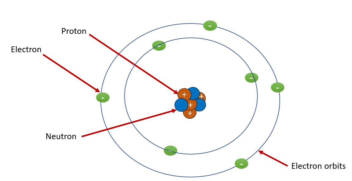
    3. Rutherford’s Nuclear Model (1911)

    Through his gold foil experiment, Rutherford observed that most alpha particles passed straight through the foil, but some were deflected at large angles. He concluded:

    • The atom is mostly empty space.

    • It has a small, dense, positively charged nucleus at the center.

    • Electrons orbit this nucleus, similar to how planets orbit the sun.

    🔹 Limitation: According to classical physics, orbiting electrons should lose energy and spiral into the nucleus. Yet, atoms are stable — something this model couldn’t explain.


    4. Bohr’s Model (1913)

    Niels Bohr built on Rutherford’s model using ideas from quantum theory. He proposed:

    • Electrons orbit the nucleus in discrete energy levels (shells) without radiating energy.

    • Electrons can jump between levels by absorbing or emitting a fixed amount of energy (a quantum).

    • This model successfully explained the line emission spectrum of hydrogen.

    🔹 Limitation: It worked well only for hydrogen and single-electron systems. Could not accurately predict spectra for multi-electron atoms.


    5. Quantum Mechanical Model (Modern Model)

    The current model of the atom is based on quantum mechanics. It describes atoms more accurately by treating electrons as both particles and waves.

    Key features:

    • Electrons are found in orbitals, not fixed paths. These are regions where electrons are likely to be found.

    • Schrödinger’s Equation is used to describe these orbitals, but for A/L, only a conceptual understanding is needed — no math required.

    • The Heisenberg Uncertainty Principle says we cannot know both the exact position and momentum of an electron at the same time — this highlights the probabilistic nature of electron behavior.

    • Wave-particle duality means electrons behave both like particles and waves, a concept crucial to understanding modern atomic structure.

    This model provides a much more accurate and detailed view of atoms, especially for multi-electron elements.


    Summary Table of Atomic Models

  • Unit Operations Overview: Types and Real-World Applications in Chemical Engineering

    Unit Operations Overview: Types and Real-World Applications in Chemical Engineering

    Unit operations are the fundamental building blocks of chemical engineering processes. Understanding these operations and their practical applications helps engineers design, optimize, and troubleshoot complex industrial systems efficiently.


    What Are Unit Operations?

    Unit operations refer to the basic physical and chemical steps involved in processing raw materials into finished products. These include processes such as mixing, heat transfer, separation, and chemical reactions, which recur across many industries.


    Comprehensive List of Unit Operations and Their Real-World Applications

    1. Fluid Flow and Transport Operations

    Pumping and Compressing

    Description: Mechanical methods used to move liquids or gases through pipelines and systems. Pumps transfer liquids, while compressors increase gas pressure.
    Application: Transporting crude oil through pipelines, circulating cooling water in power plants, air compression in chemical reactors.

    Mixing and Agitation

    Description: The process of combining multiple fluids or solids to form a uniform mixture or suspension.
    Application: Blending chemicals in pharmaceutical production, mixing paints and coatings, homogenizing dairy products.

    Filtration

    Description: The separation of solids from liquids or gases using a porous medium or filter.
    Application: Removing solids from wastewater, clarifying beverages, purifying pharmaceuticals.

    Sedimentation and Clarification

    Description: Using gravity to settle suspended solids from liquids to clarify the fluid.
    Application: Settling solids in water treatment plants, separating solids in mining slurry processing.

    Centrifugation

    Description: The use of centrifugal force to separate components based on density differences.
    Application: Separating cream from milk, solid-liquid separation in chemical processing, biomass harvesting in biotechnology.


    2. Heat Transfer Operations

    Heat Exchangers

    Description: Devices designed to efficiently transfer heat from one fluid to another without mixing them.
    Application: Recovering heat in power plants, cooling petroleum fractions in refineries, heating process fluids in chemical plants.

    Evaporation

    Description: The process of vaporizing a liquid to concentrate the remaining solution.
    Application: Concentrating fruit juices, desalination of seawater, concentrating chemical solutions.

    Condensation

    Description: The transformation of vapor into liquid to recover heat or separate components.
    Application: Condensing steam in power plants, recovering solvents in chemical processes.

    Drying

    Description: Removing moisture from solids or liquids by evaporation or other means.
    Application: Drying pharmaceuticals, food products like grains and powders, chemical intermediates.


    3. Mass Transfer Operations

    Distillation

    Description: Separation of components in a liquid mixture based on differences in boiling points.
    Application: Separating crude oil into gasoline and diesel, alcohol purification, solvent recovery.

    Absorption

    Description: Transfer of a gas component into a liquid solvent.
    Application: Removing CO₂ from flue gases, scrubbing ammonia from air streams.

    Extraction

    Description: Separation process where a component is transferred from one liquid phase to another immiscible liquid phase.
    Application: Extracting caffeine from coffee beans, separating valuable metals from ores.

    Leaching

    Description: Removal of soluble substances from solids by washing with a solvent.
    Application: Removing sugar from sugarcane, mineral recovery from ores.

    Adsorption

    Description: Adhesion of atoms, ions, or molecules from a gas, liquid, or dissolved solid onto a surface.
    Application: Purifying gases, removing impurities from water, solvent recovery.


    4. Chemical Reaction Operations

    Batch Reactors

    Description: Closed vessels where reactions occur in discrete batches with specific reaction times.
    Application: Pharmaceutical synthesis, specialty chemicals production.

    Continuous Stirred Tank Reactors (CSTRs)

    Description: Reactors where reactants are continuously fed and products continuously removed, with mixing to maintain uniform composition.
    Application: Large-scale chemical manufacturing, wastewater treatment.

    Plug Flow Reactors (PFRs)

    Description: Tubular reactors where reactants flow in one direction with no back-mixing, approximating a “plug” flow.
    Application: Petrochemical cracking, polymerization processes.


    5. Size Reduction and Size Enlargement

    Crushing and Grinding

    Description: Mechanical processes to reduce particle size for better handling and processing.
    Application: Mineral processing, cement manufacturing, food milling.

    Screening and Classification

    Description: Separation of particles based on size using screens or classifiers.
    Application: Sorting ores, separating powders in pharmaceuticals.

    Pelletizing and Agglomeration

    Description: Processes to increase particle size by binding smaller particles into larger pellets or agglomerates.
    Application: Making fertilizer pellets, briquetting coal dust.


    6. Other Important Unit Operations

    Heat Treatment

    Description: Controlled heating and cooling of materials to alter their physical and mechanical properties.
    Application: Annealing metals, curing polymers.

    Crystallization

    Description: Formation of solid crystals from a homogeneous solution.
    Application: Purifying sugar, manufacturing pharmaceuticals.

    Ion Exchange

    Description: A reversible chemical reaction where ions are exchanged between a solution and an ion exchange resin or material.
    Application: Water softening, purification of pharmaceuticals.


    Summary Table: Unit Operations and Applications


    Why Mastering Unit Operations Matters

    • Helps in process design and scale-up from lab to industry.

    • Enables problem-solving by isolating issues to specific process steps.

    • Improves energy efficiency, safety, and product quality.

    • Provides a universal language for chemical engineers across industries.


    Conclusion

    Unit operations are the cornerstone of chemical engineering, forming a toolkit to design and analyze virtually every industrial process. Whether it’s refining oil, producing pharmaceuticals, or treating water, understanding these operations and their applications is critical for engineers aiming for innovation and operational excellence.

  • Process Flow Diagrams (PFDs) and Drawings in Chemical Engineering: A Complete Guide

    Process Flow Diagrams (PFDs) and Drawings in Chemical Engineering: A Complete Guide

    In chemical engineering, drawings and Process Flow Diagrams (PFDs) are vital for designing, analyzing, and operating chemical processes. They provide a clear visual representation of the flow of materials, major equipment, and process parameters, making complex systems easier to understand and manage.

    What is a Process Flow Diagram (PFD)?

    A Process Flow Diagram (PFD) is a foundational document in chemical and process engineering that visually represents the major components and flow of a chemical process. It offers a high-level, simplified schematic of a process plant, emphasizing the main equipment units, process streams, and interconnections without diving into detailed instrumentation or piping layouts.

    PFDs are typically developed during the conceptual and front-end engineering design (FEED) stages and serve as a communication bridge between process engineers, plant operators, management, and stakeholders.

    1.0 Key Features of a PFD

    A well-constructed PFD typically includes the following elements:

    1. Major Process Equipment


    The diagram shows core unit operations and equipment used in the process, often represented by standardized symbols. These include:

    • Reactors (e.g., CSTR, PFR)

    • Heat exchangers (e.g., shell-and-tube, plate)

    • Distillation columns

    • Pumps and compressors

    • Furnaces and boilers


    Each equipment item is labeled with a unique equipment tag number (e.g., P-101 for a pump, E-201 for a heat exchanger).

    2. Process Streams

    Lines connecting equipment illustrate the directional flow of process materials—gases, liquids, vapors, or slurries.

    • Arrows show flow direction.

    • Stream numbers identify each stream uniquely.

    • Basic stream data are often shown near the stream line (e.g., flow rate, temperature, pressure, and composition).


    3. Operating Conditions


    Key process parameters are listed to provide insight into operating regimes:

    • Temperature (°C or °F)

    • Pressure (bar, atm, or psi)

    • Mass or volumetric flow rates (kg/h, m³/h, mol/s, etc.)


    This data is typically displayed at stream junctions or in a stream table accompanying the diagram.

    4. Basic Control Elements (Optional)


    While detailed control systems are reserved for Piping and Instrumentation Diagrams (P&IDs), a PFD may optionally show:

    • Level or pressure control valves

    • Major control loops for critical units

    These are depicted using simplified symbols to avoid cluttering the schematic.

    5. Process and Equipment Identification


    To ensure clear communication across teams:

    • Stream numbers (e.g., S-101) help track process data.

    • Equipment ID tags correspond to design specifications and datasheets.

    • Process names or unit sections clarify the function of each area (e.g., “Dehydration Section”, “Reactor Loop”).


    Example: PFD of a Polymer Production Process


    Figure 4: Simplified Process Flow Diagram for Polymer Production (Small-Scale Process) (Towler and Sinnott 2013).

    This sample illustrates a basic PFD for a polymerization process, showing raw material feed tanks, a reactor, heat recovery, product separation, and final storage.

    2.0 Purpose and Applications of a PFD


    A Process Flow Diagram serves multiple purposes across the lifecycle of a chemical plant:

    1. Process Understanding

    PFDs provide engineers, operators, and management with a bird’s-eye view of how raw materials are transformed into products.

    2. Conceptual & Front-End Design

    Engineers use PFDs during feasibility studies and early-stage design to:

    • Evaluate alternative process routes

    • Identify major equipment needs

    • Estimate capital and operating costs


    3. Communication Across Teams

    PFDs act as a common visual language between process engineers, mechanical designers, instrumentation specialists, and safety teams.

    4. Safety and Hazard Reviews

    They are essential in HAZOP (Hazard and Operability) studies to identify process risks and evaluate mitigation strategies.

    5. Operator Training

    Simplified views of the process help train new operators and maintenance staff by illustrating the flow of materials and major unit functions.

    Final Thoughts


    A Process Flow Diagram is not just a drawing—it’s a blueprint for process design, optimization, and communication. It sets the foundation for deeper analysis using tools like:

    • Mass and energy balances

    • Equipment sizing

    • Control strategy development

    • Process simulation

    Mastering PFDs is essential for chemical engineers, process designers, and plant operators alike.

    1. Major Equipment Symbols


    2. Stream Lines and Flow Direction

    • Arrowed Lines: Represent the flow direction of process streams (liquid, gas, slurry).

    • Line Types:


    3. Valve Symbols

    4. Instrumentation Symbols (Basic)

    Tips for Creating Your Own PFD

    • Use standardized symbols from ISA (Instrumentation Society of America) or ISO for consistency.

    • Keep the diagram clear and simple, focusing on major equipment and flow.

    • Label streams and equipment clearly with names or numbers.

    • Include operating conditions like temperature, pressure, and flow rate where relevant.

    • Software tools like Microsoft Visio, Lucidchart, AutoCAD P&ID, or specialized chemical engineering software can simplify PFD creation.

    3. Other Important Drawings in Chemical Engineering

    Besides PFDs, several other drawings are essential in the design and operation of chemical plants:

    1. Piping and Instrumentation Diagram (P&ID)

    • Detailed schematic showing all piping, valves, instrumentation, and control systems.

    • Includes pipe sizes, valve types, instrument locations, and control loops.

    • Used for plant construction, operation, and maintenance.

    2. Equipment Drawings

    • Mechanical drawings of individual equipment showing dimensions, materials, and nozzle placements.

    • Used for equipment fabrication and inspection.

    3. Layout Drawings / Plot Plans

    • Show the physical placement of equipment, piping routes, buildings, and utilities on site.

    • Used for construction planning and safety.

    4. Electrical and Control Drawings

    • Detail wiring diagrams, control panel layouts, and automation logic.

    • Critical for instrumentation and control system installation.

    Summary Table: Chemical Engineering Drawings


    Why Are PFDs Important?

    • Simplify complex processes for better understanding and communication.

    • Form the basis for creating detailed P&IDs.

    • Assist in process design, troubleshooting, and safety reviews.

    • Essential documentation for regulatory compliance.


    Conclusion

    Process Flow Diagrams (PFDs) are the cornerstone of chemical process design and communication. Along with P&IDs and other detailed drawings, they provide engineers and operators with the information necessary to build, run, and maintain safe and efficient chemical plants.

    Reference

    • Towler G, Sinnott R. Chemical Engineering Design: Principles, Practice and Economics of Plant and Process Design. 2nd ed. Boston: Elsevier; 2013.
  • Heat Transfer Basics: Fundamentals Every Engineer Should Know

    Heat Transfer Basics: Fundamentals Every Engineer Should Know

    Heat transfer is a fundamental concept in engineering that describes how thermal energy moves from one place to another. It plays a critical role in numerous applications such as power generation, chemical processing, HVAC systems, electronics cooling, and more.

    Understanding the basics of heat transfer is essential for designing efficient systems that manage temperature effectively, improve energy efficiency, and ensure safety.


    What is Heat Transfer?

    Heat transfer is the process by which thermal energy moves due to temperature differences. Heat always flows from a region of higher temperature to a region of lower temperature until thermal equilibrium is reached.


    Three Modes of Heat Transfer

    Heat can be transferred by three primary mechanisms:

    1. Conduction

    • Definition: Transfer of heat through a solid material or between materials in direct contact without the movement of the material itself.

    • How it works: Heat energy is transferred from molecule to molecule by vibration and collision.

    • Real-World Examples:

      • When you hold a metal spoon in a hot cup of coffee, the handle gets warm due to conduction.

      • Heat moving through the walls of a building, affecting indoor temperatures.

      • Cooking food on a stovetop pan where heat transfers from the burner to the pan and then to the food.

    Key equation: Fourier’s Law

    Where:

    • Q = heat transfer rate (W)

    • k = thermal conductivity of the material (W/m·K)

    • A = cross-sectional area (m²)

    • dT/dX = temperature gradient (K/m)


    2. Convection

    • Definition: Transfer of heat by the movement of fluid (liquid or gas).

    • How it works: Heated fluid expands, becomes less dense, and rises while cooler fluid sinks, creating a circulation pattern.

    • Types:

      • Natural convection: Driven by buoyancy forces due to density differences (e.g., warm air rising)

      • Forced convection: External means like fans or pumps move the fluid (e.g., cooling of a car radiator)

    • Real-World Examples:

      • Warm air rising from a radiator heating a room (natural convection).

      • Air conditioning systems using fans to circulate cooled air (forced convection).

      • Boiling water circulating in a pot where hot water rises and cooler water descends.

    Key equation: Newton’s Law of Cooling

    Where:

    • Q = heat transfer rate (W)

    • h = convective heat transfer coefficient (W/m²·K)

    • A = surface area (m²)

    • Ts = surface temperature (K)

    • T∞ = fluid temperature away from surface (K)


    3. Radiation

    • Definition: Transfer of heat through electromagnetic waves without involving particles or medium.

    • How it works: All objects emit radiant energy depending on their temperature.

    • Real-World Examples:

      • Feeling the warmth of the sun on your skin.

      • Heat radiating from a hot stovetop burner or fireplace.

      • Infrared heaters warming a room by emitting radiant heat.

    Key equation: Stefan-Boltzmann Law

    Where:

    • ϵ (epsilon) = emissivity of surface (dimensionless, 0 to 1)

    • σ (sigma) = Stefan-Boltzmann constant ()

    • A = surface area (m²)

    • Ts = Surface temperature (absolute) (K)

    • T∞

    Heat Transfer in Engineering Applications

    • Heat exchangers: Transfer heat between two or more fluids at different temperatures, using conduction and convection. Example: Condensers in power plants.

    • Insulation design: Minimizes heat loss/gain through conduction. Example: Insulating pipes and building walls.

    • Cooling systems: Use convection and radiation to dissipate heat from electronics or engines. Example: Car radiator cooling engine coolant.

    • Solar energy systems: Use radiation principles for heat collection. Example: Solar thermal water heaters.


    Summary


    Final Thoughts

    Mastering heat transfer basics helps engineers optimize designs, save energy, and enhance safety. Whether it’s improving the efficiency of a heat exchanger or preventing overheating in electronics, understanding how heat moves is crucial.

  • Plant Safety: A Foundation for Chemical Plant Safety Excellence

    Plant Safety: A Foundation for Chemical Plant Safety Excellence

    In the chemical processing industry, safety is not just a regulatory requirement—it’s a lifeline. Chemical plants deal with hazardous substances, high pressures, extreme temperatures, and reactive systems that can pose serious threats if not managed properly. A single lapse can lead to catastrophic consequences, affecting people, the environment, and business sustainability.

    This guide offers a comprehensive learning structure and explains the critical safety systems, hazards, tools, and best practices every chemical engineer, technician, or plant operator should know.


    Learning Structure for Plant Safety

    To build a strong safety culture, you need a structured educational approach. Below is a framework that guides safety training and competency development in chemical industries.


    1. Introduction to Plant Safety

    • Why Safety Matters:
      Safety is the foundation of sustainable operations. It prevents accidents, protects employees, preserves assets, and enhances plant efficiency.

    • Basic Safety Terminology:
      Terms like hazard, risk, near-miss, incident, exposure, and mitigation must be well understood to foster clear communication.

    Hazard – A potential source of harm or danger.
    Example: A flammable liquid stored near a heat source.

    Risk – The chance that a hazard will cause harm, considering the likelihood and severity.
    Example: The risk of fire increases if the flammable liquid is not stored properly.

    Near-Miss – An unplanned event that did not cause harm but had the potential to do so.
    Example: A worker slips but regains balance and avoids a fall.

    Incident – An event that causes or could cause harm, injury, damage, or loss.
    Example: A chemical spill that causes skin burns or equipment damage.

    Exposure – The contact or presence of a person with a hazard (chemical, physical, or biological).
    Example: Inhaling solvent vapors or touching a hot surface.

    Mitigation – Actions taken to reduce the severity or impact of a hazard or incident.
    Example: Installing gas detectors and emergency shutdown systems.

    • Types of Hazards:


    2. Hazard Identification and Risk Assessment

    • Methods of Hazard Identification:
      Use checklists, job safety analysis (JSA), audits, and inspections to detect hazards before they cause harm.

    • Risk Assessment Process:
      Evaluate likelihood × severity to prioritize controls.

    • Hierarchy of Controls:

    1. Elimination

    Remove the hazard entirely from the workplace.
    Example: Replace a toxic chemical process with a safer method.

    2. Substitution

    Replace the hazard with a less dangerous one.
    Example: Use a less volatile solvent.

    3. Engineering Controls

    Physically isolate people from the hazard.
    Example: Enclose equipment, install ventilation or interlocks.

    4. Administrative Controls

    Change how people work to reduce exposure.
    Example: Training, shift rotations, signage, SOPs.

    5. Personal Protective Equipment (PPE)

    Last line of defense—protect the worker.
    Example: Gloves, goggles, respirators.


    3. Safety Policies, Procedures, and Standards

    • Developing Policies:
      Establish clear goals, responsibilities, and enforcement mechanisms.

    • Roles and Responsibilities:

      • Management: Resource allocation and accountability

      • Supervisors: Daily oversight and team training

      • Employees: Safe conduct, reporting, and cooperation

    • Safety Management Systems (SMS):
      Frameworks like ISO 45001 integrate safety into daily operations.

    • Legal Compliance:
      Adhere to OSHA, EPA, and local regulations to avoid fines and improve risk control.


    4. Personal Protective Equipment (PPE)

    PPE is vital for individual protection when other controls cannot eliminate risks.

    • Types of PPE:

    • Selection and Use:
      Based on hazard type and job requirement. Must be inspected regularly and fitted correctly.

    • Limitations:
      PPE does not eliminate hazards, only shields workers.


    5. Machine and Equipment Safety

    • Guarding & Interlocks:
      Protect operators from moving parts and accidental contact.

    • Lockout/Tagout (LOTO):
      Ensures complete isolation of energy sources during maintenance.

    • Standard Operating Procedures (SOPs):
      Documented safe practices for routine and emergency operations.

    • Inspection & Maintenance:
      Preventive upkeep of machinery avoids mechanical failures and unexpected downtime.


    6. Chemical Safety

    • Material Safety Data Sheets (MSDS / SDS):
      Provide information on handling, exposure, first aid, storage, and reactivity.

    • Safe Handling and Storage:
      Segregate incompatible chemicals, use proper containers, and label everything clearly.

    • Spill Control:
      Include containment trays, spill kits, and trained response teams.

    • Hazard Communication:
      Use signage, labels, and visual cues throughout the plant.


    7. Emergency Preparedness and Response

    • Types of Emergencies:
      Fire, explosion, chemical leaks, toxic gas release, medical emergencies

    • Emergency Action Plans (EAP):
      Step-by-step plans for evacuation, containment, and communication

    • Evacuation Routes & Muster Points:
      Clearly marked and regularly drilled

    • Firefighting Systems:
      Extinguishers, fire blankets, deluge systems, hydrants

    • First Aid:
      CPR-trained staff, stocked first-aid kits, and emergency eyewash stations


    8. Safety Training and Competency

    • Needs Assessment:
      Identify gaps based on job roles and site risks.

    • Training Delivery:
      Blended learning with classroom, online, and on-the-job methods

    • Safety Culture:
      Promote accountability, communication, and proactive behavior.

    • Competency Testing:
      Verify understanding through assessments, certifications, or simulations.


    9. Environmental Safety and Health

    • Waste Management:
      Segregation, treatment, and disposal of hazardous and non-hazardous waste

    • Pollution Prevention:
      Emission control, water conservation, solvent recovery

    • Health Hazards:
      Address noise, vibration, temperature, confined space entry

    • Ergonomics:
      Design tasks to minimize repetitive stress and fatigue


    10. Incident Reporting and Investigation

    • Reporting Procedures:
      Encourage prompt reporting of incidents and near misses

    • Root Cause Analysis (RCA):
      Use 5 Whys, Fishbone Diagrams to uncover systemic causes


    • Corrective/Preventive Actions (CAPA):
      Implement changes and monitor results

    • Performance Metrics:
      Track KPIs like TRIR, LTIR, near miss frequency


    11. Continuous Improvement in Safety

    • Audits & Inspections:
      Conduct regular reviews of systems and equipment

    • Safety Committees:
      Engage employees in identifying problems and solutions

    • Feedback Loops:
      Listen to workers—they often spot issues early

    • Use of Technology:
      Drones for inspection, SCADA systems, AI monitoring


    Why Safety Is Essential in Chemical Plants

    Without robust safety protocols, chemical plants can face:

    • Fires and Explosions

    • Toxic Releases

    • Operational Downtime

    • Injuries or Fatalities

    • Environmental Damage

    • Reputational and Legal Consequences

    These risks make safety not just ethical—but essential for business continuity.


    Common Hazards in the Chemical Industry

    • Flammable gases and liquids

    • Reactive chemicals

    • High pressure vessels

    • Toxic substances

    • Mechanical hazards from rotating or pressurized equipment

    • Ergonomic stress and fatigue

    • Electrical hazards and arc flashes


    Safety Tools and Systems in Chemical Plants

    Chemical plants are protected by multiple layers of safety systems, categorized as:

    1. Process Safety Systems

    • Pressure Relief Devices (PRDs): Prevent vessel ruptures

    • Emergency Shutdown Systems (ESDs): Automated equipment shutdown

    • Safety Instrumented Systems (SIS): Perform critical actions like closing valves or tripping pumps

    • Inert Gas Blanketing: Suppresses flammable vapor formation

    • Explosion Vents/Flame Arrestors: Release pressure and contain ignition

    2. Personal Protective Equipment (PPE)

    • Chemical suits, gloves, respirators, eye and face protection

    3. Gas and Fire Detection Systems

    • Fixed Detectors: For H₂S, CH₄, VOCs

    • Portable Monitors: For confined space entry

    • Smoke/Flame Detectors: Trigger suppression systems

    4. Fire and Explosion Protection Systems

    5. Control and Monitoring Systems

    • DCS (Distributed Control System): Manages process plant

    • PLC (Programmable Logic Controller): Controls specific units

    • SCADA: Supervises remote systems

    • Alarms: Alert deviations in pressure, temperature, flow, etc.

    6. Emergency Response and Escape Systems


    Best Practices for Safety in Chemical Plants

    • Conduct Process Hazard Analyses (PHA): HAZOP, What-If, Fault Tree

    • Follow Permit-to-Work Systems: Hot work, confined space, electrical

    • Standard Operating Procedures (SOPs): Well-documented and reviewed

    • Train Employees Regularly: Safety drills, PPE use, hazard awareness

    • Preventive Maintenance: Equipment, valves, sensors

    • Plan and Practice Emergencies: Evacuation, communication, firefighting


    Regulatory Compliance

    Plants must comply with:

    Compliance ensures legal operation and promotes industry best practices.


    Final Thoughts

    Safety in chemical plants is not optional—it is mission-critical. An effective safety strategy protects lives, prevents environmental disasters, enhances efficiency, and ensures long-term profitability.

    With well-structured learning, smart systems, and a proactive culture, zero incidents is not a dream—it’s an achievable standard.

    “You can’t manufacture safety—but you can engineer it into every step.”

  • Mass and Energy Balances: Core Concepts for Chemical Engineers

    Mass and Energy Balances: Core Concepts for Chemical Engineers

    In the world of chemical and process engineering, mass and energy balances are essential tools for designing, analyzing, and optimizing processes. Whether you’re sizing equipment, improving efficiency, or reducing environmental impact, a strong understanding of material and energy flows is critical.

    This guide breaks down the principles of mass and energy balances, how they are applied, and why they are fundamental to every chemical engineer’s toolkit.


    🔍 What Are Mass and Energy Balances?

    📌 Mass Balance (Material Balance)

    A mass balance is a quantitative account of all the material entering, leaving, accumulating, or being generated within a process unit. Based on the Law of Conservation of Mass, it ensures that:

    Input = Output + Accumulation – Consumption/Generation

    📌 Energy Balance

    An energy balance applies the First Law of Thermodynamics, which states that energy can neither be created nor destroyed. In a steady-state process (no accumulation):

    Energy In = Energy Out

    Energy balances include forms of energy such as:

    • Sensible heat

    • Latent heat

    • Work done (e.g., shaft work)

    • Chemical reaction energy


    🧮 General Mass Balance Equation

    Input+Generation=Output+Accumulation

    This equation applies to any material system and accounts for flow, chemical reactions, and storage.

    Special Cases:

    • Steady-State, Non-Reactive Systems:

    Input=Output

    No chemical reaction or accumulation occurs; mass simply flows through.

    • Steady-State, Reactive Systems:

      Input+Generation (by reaction)=Output

    Chemical reactions alter the mass flow by generating or consuming species, but there’s still no accumulation.


    General Energy Balance Equation

    Energy InEnergy Out=ΔEnergy Stored

    This is the first law of thermodynamics applied to a control volume.

    Components of Energy Inputs and Outputs:

    • Heat (Q) – energy transferred due to temperature difference

    • Work (W) – includes shaft work, electrical work, etc.

    • Enthalpy of material streams (H) – internal energy carried by flowing matter

    For Open Systems (e.g., continuous-flow processes):

    Q+W+Hin=Hout

    In practical terms, energy inputs and outputs may include:

    • Heat (Q)

    • Work (W)

    • Enthalpy of streams (H)

    At steady state, the energy added to the system as heat, work, and enthalpy of incoming streams equals the energy leaving in outgoing streams.


    🛠️ Types of Mass and Energy Balances


    🏭 Industrial Applications of Mass and Energy Balances


    Why Are Mass and Energy Balances Important?

    ✅ Ensure process safety and efficiency
    ✅ Support equipment sizing and design
    ✅ Minimize waste and energy losses
    ✅ Enable cost-effective operation
    ✅ Form the basis for process simulation software (e.g., Aspen Plus, HYSYS)


    Example 1: Simple Steady-State Mass Balance

    Problem: A mixing tank receives 100 kg/h of stream A and 50 kg/h of stream B. What is the outlet flowrate?

    Solution:

    Mass Balance (Non-Reactive, Steady-State):

    Input=Output100+50=150kg/h

    Therefore, the total output is 150 kg/h.


    Example 2: Energy Balance (Sensible Heat)

    Problem: How much energy is required to heat 1000 kg/h of water from 25°C to 90°C?

    Use:


    Example 3: Mass Balance in a Mixing Process

    Problem:
    A process blends two input streams of ethanol and water to make a solution.

    • Stream A: 60 kg/h of 100% ethanol

    • Stream B: 40 kg/h of 100% water

    Objective: Determine the composition of the outlet stream in terms of ethanol and water percentages.

    Solution:

    Total mass in = 60 kg/h (ethanol) + 40 kg/h (water) = 100 kg/h

    • Ethanol in outlet = 60 kg/h → (60/100) × 100 = 60% ethanol

    • Water in outlet = 40 kg/h → (40/100) × 100 = 40% water

    Answer: Outlet stream = 100 kg/h, composed of 60% ethanol and 40% water


    Example 4: Energy Balance in a Heater

    Problem:
    Calculate the energy required to heat 5000 kg/h of water from 25°C to 75°C in a heat exchanger.

    Given:

    • Specific heat of water, Cp = 4.18 kJ/kg·°C

    • No phase change (sensible heating only)

    Solution:

    Use the energy balance formula:


    ✅ Best Practices for Performing Balances

    • Always draw a process flow diagram (PFD)

    • Define a system boundary

    • Use consistent units throughout the calculation

    • Apply dry/wet basis, mass/mole basis, or steady/unsteady terms correctly

    • Account for reactions, phases, and heat losses if applicable


    Final Thoughts

    Mass and energy balances are the backbone of chemical engineering analysis. They help engineers predict process behavior, optimize system performance, and ensure sustainability in industrial operations.

    Whether you’re designing a new plant or troubleshooting an existing system, mastering this fundamental skill will set you apart as a process engineer.

  • Chemical Reactors – Types and Applications in the Process Industry

    Chemical Reactors – Types and Applications in the Process Industry

    Chemical reactors are the heart of chemical process industries, where raw materials are transformed into valuable products through controlled chemical reactions. Understanding different types of chemical reactors and their industrial applications is essential for chemical engineers, plant designers, and process technologists.

    This post explains the classification of reactors, their working principles, advantages, limitations, and common industrial uses.


    🔍 What is a Chemical Reactor?

    A chemical reactor is a vessel designed to contain and control chemical reactions. It facilitates the optimal interaction of reactants, temperature, pressure, catalysts, and mixing to produce desired chemical transformations.

    Reactors vary in design and operation depending on:

    • Reaction kinetics

    • Heat and mass transfer

    • Physical state of reactants (gas, liquid, solid)

    • Batch or continuous operation


    Main Types of Chemical Reactors

    1. Batch Reactor

    Working Principle: All reactants are loaded at the start, and the reaction proceeds for a fixed time before products are removed.

    Features:

    • No inflow/outflow during the reaction

    • Excellent for small-scale or specialty chemicals

    • Easy to operate and clean

    Applications:

    • Pharmaceutical production

    • Specialty chemicals

    • Polymer synthesis

    • Research & development


    2. Continuous Stirred Tank Reactor (CSTR)

    Working Principle: Reactants are continuously fed, and products continuously removed. Mixing is maintained to ensure uniform composition.

    Features:

    • Steady-state operation

    • Good for liquid-phase reactions

    • Suitable for slow reactions

    Applications:

    • Wastewater treatment

    • Biochemical fermentation

    • Homogeneous liquid reactions


    3. Plug Flow Reactor (PFR) / Tubular Reactor

    Working Principle: Reactants flow through a tubular reactor without back-mixing. Composition and temperature change along the length.

    Features:

    • High conversion efficiency

    • Short residence time

    • Suitable for fast reactions

    Applications:

    • Petrochemical processing

    • Gas-phase reactions

    • Polymer and plastic manufacturing


    4. Packed Bed Reactor (PBR)

    Working Principle: Reactants flow through a bed of solid catalyst particles.

    Features:

    • Used mainly for catalytic reactions

    • High surface area for reactions

    • Pressure drop can be an issue

    Applications:

    • Catalytic cracking in refineries

    • Ammonia and methanol synthesis

    • Hydrogenation processes


    5. Fluidized Bed Reactor

    Working Principle: Solid catalyst particles are suspended in an upward flow of gas or liquid.

    Features:

    • Excellent heat and mass transfer

    • Uniform temperature distribution

    • Suitable for exothermic reactions

    Applications:

    • Combustion processes

    • Fluid catalytic cracking (FCC)

    • Polymerization


    6. Semi-Batch Reactor

    Working Principle: A hybrid between batch and continuous reactors. One reactant is fed during the reaction while others are loaded at the start.

    Features:

    • Useful for controlling reaction rates

    • Safer for highly exothermic reactions

    Applications:

    • Controlled polymerization

    • Neutralization reactions

    • Gas-liquid reactions


    7. Photochemical and Electrochemical Reactors

    Specialty Reactors designed for:

    • Light-driven reactions (photoreactors)

    • Electrolysis or redox reactions (electrochemical cells)

    Applications:

    • Hydrogen generation

    • Water treatment

    • Photocatalysis

    • Green chemistry innovations


    Factors Influencing Reactor Selection


    Real-World Applications by Industry


    ✅ Summary: Choosing the Right Reactor

    The choice of reactor directly affects yield, selectivity, energy efficiency, and safety. Engineers must consider reaction kinetics, phase behavior, temperature control, and cost when designing or selecting a reactor system.

    From simple batch systems to complex multiphase catalytic reactors, chemical reactors drive the innovation and sustainability of modern chemical processes.

  • Distillation Principles: The Foundation of Separation in Chemical Engineering

    Distillation Principles: The Foundation of Separation in Chemical Engineering

    Distillation is one of the most fundamental and widely used separation processes in the chemical and process industries. From refining crude oil to producing high-purity solvents, the principles of distillation form the backbone of countless industrial operations.

    This article explains the core principles of distillation, types of distillation, key components, and factors that influence efficiency — ideal for students, professionals, and anyone seeking to understand this essential process.


    🔍 What Is Distillation?

    Distillation is a thermal separation process that separates components of a liquid mixture based on differences in their boiling points. It involves:

    1. Heating the liquid mixture to form vapor.

    2. Condensing the vapor back to liquid.

    3. Collecting the condensed product separately.

    The component with the lower boiling point vaporizes first and can be condensed and separated, while the higher boiling components remain in the liquid phase longer.


    🌡️ Fundamental Distillation Principles

    1. Volatility and Boiling Point

    • More volatile components have lower boiling points and evaporate more easily.

    • Less volatile components have higher boiling points and remain in the liquid phase.

    2. Vapor-Liquid Equilibrium (VLE)

    At a given pressure and temperature, a liquid and its vapor reach an equilibrium. The composition of the vapor differs from the liquid, allowing selective separation.

    3. Raoult’s Law and Dalton’s Law

    • Raoult’s Law: The partial pressure of a component is proportional to its mole fraction in the liquid and its pure component vapor pressure.

    • Dalton’s Law: Total vapor pressure is the sum of the partial pressures of all components.

    These laws describe how the composition of the vapor differs from that of the liquid, which is key to separation.


    Key Components of a Distillation Column


    🔁 Types of Distillation Processes

    1. Simple Distillation

    • Used when the boiling point difference is large (>25°C).

    • Limited to separating two components or purifying a single volatile compound.

    2. Fractional Distillation

    • Used for separating mixtures with close boiling points.

    • Utilizes multiple vaporization-condensation cycles in a tall column with trays or packing.

    3. Vacuum Distillation

    • Conducted under reduced pressure to lower boiling points.

    • Ideal for heat-sensitive compounds like oils and polymers.

    4. Steam Distillation

    • Uses steam to carry volatile components from a mixture.

    • Common in essential oil extraction.

    5. Azeotropic and Extractive Distillation

    • Used when azeotropes prevent complete separation by standard methods.

    • Azeotropic distillation adds an entrainer to break the azeotrope.

    • Extractive distillation uses a solvent to change relative volatilities.


    📉 Distillation Curve

    A distillation curve plots the temperature of the distillate versus the volume of distillate collected. It provides a visual representation of how components separate over time — especially in crude oil refining and petrochemical analysis.


    Factors Affecting Distillation Efficiency

    1. Reflux Ratio
      Higher reflux improves separation but increases energy consumption.

    2. Column Internals
      Tray design (sieve, valve, bubble-cap) or packing type (structured, random) impacts mass transfer.

    3. Heat Input
      Too little = poor separation; too much = flooding or entrainment.

    4. Pressure
      Lower pressure reduces boiling points; used in vacuum distillation.

    5. Feed Composition & Location
      Optimal feed location ensures best efficiency and minimal remixing.

    Real-World Applications of Distillation


    Summary: Why Distillation Matters

    Distillation remains the most versatile and essential separation technique in chemical engineering. Understanding the underlying principles of vapor-liquid equilibrium, relative volatility, and thermodynamics allows engineers to design, operate, and optimize distillation systems for maximum performance and minimal cost.

  • Heat Exchangers: Common Failures, Causes, and Prevention Strategies

    Heat exchangers are vital to nearly every industry, including chemical processing, power generation, oil and gas, HVAC, and pharmaceuticals. These systems operate based on core principles of thermodynamics — transferring heat from one fluid to another without mixing.

    Despite having no moving parts, heat exchangers are still prone to various types of failures due to thermal, mechanical, and chemical stresses. This guide explores the most common heat exchanger failures, their causes, and how engineers can prevent them to ensure operational efficiency and long-term reliability.


    How Heat Exchangers Work

    Heat exchangers enable thermal energy transfer between two or more fluids. This process follows the Zeroth, First, and Second Laws of Thermodynamics. They are classified by:

    • Fluid Flow Configuration: Co-current, counter-current, crossflow, hybrid

    • Construction Method: Recuperative vs. regenerative, direct vs. indirect

    • Heat Transfer Mechanism: Single-phase or two-phase


    Common Industrial Heat Exchanger Types


    Common Heat Exchanger Failures and How to Prevent Them

    1. Mechanical Failures

    1.1 Metal Erosion

    • Cause: High fluid velocity erodes tube walls, especially at bends and entrances.

    • Symptoms: Horseshoe-shaped erosion, thinning walls.

    • Prevention:

      • Control inlet velocities.

      • Use erosion-resistant materials.

      • Add impingement baffles at high-velocity zones.

    1.2 Water or Steam Hammer

    • Cause: Sudden pressure surges due to rapid valve closure or steam-condensate interaction.

    • Effects: Tube rupture or collapse.

    • Prevention:

      • Install steam traps and vacuum breakers.

      • Use modulating control valves.

      • Ensure proper drainage and venting.

    1.3 Vibration

    • Cause: High shell-side velocities or nearby vibrating machinery.

    • Result: Tube wall erosion, fatigue cracks at baffles and U-bends.

    • Prevention:

      • Limit shell-side fluid velocity.

      • Use proper tube support spacing.

      • Isolate exchanger from vibration sources.

    1.4 Thermal Fatigue

    • Cause: Repeated heating and cooling cycles, especially in U-bends.

    • Prevention:

      • Minimize temperature cycling.

      • Use flexible tube materials.

      • Reduce large temperature gradients.

    1.5 Freeze-Up

    • Cause: Fluid freezing in tubes due to winter shutdown or failed temperature control.

    • Prevention:

      • Use antifreeze solutions.

      • Drain systems during shutdowns.

      • Monitor fluid temperature consistently.

    1.6 Thermal Expansion

    • Cause: Overheating with no expansion relief (e.g., steam trapped inside).

    • Prevention:

      • Install relief valves.

      • Use expansion tanks.

      • Avoid deadheading.

    1.7 Loss of Cooling Water

    • Effect: Overheating causes tubing to warp or melt.

    • Prevention:

      • Use flow sensors and alarms.

      • Maintain backup cooling systems.

      • Regular maintenance of control valves.


    2. Chemical Corrosion Failures

    2.1 Galvanic, Crevice & Pitting Corrosion

    • Cause: Electrochemical reactions from dissimilar metals or stagnant fluids.

    • Prevention:

      • Use compatible materials.

      • Avoid crevices in design.

      • Ensure proper flow rates.

    2.2 Corrosion-Fatigue

    • Combination Failure: Mechanical stress ruptures protective oxide layers, exposing metal to corrosion.

    • Prevention:

      • Control vibration and thermal cycling.

      • Choose corrosion-resistant alloys.

    2.3 Erosion-Corrosion

    • Cause: High velocity removes protective film, accelerating corrosion.

    • Prevention:

      • Reduce velocity in vulnerable areas.

      • Use surface treatments or alloy upgrades.


    3. Fouling Failures

    Fouling refers to the unwanted deposition of materials on heat exchanger surfaces, reducing efficiency and increasing pressure drops.

    💡 Pro Tip: Design with 25–30% extra surface area to account for eventual fouling in shell and tube exchangers.


    Summary of Heat Exchanger Failure Modes


    ✅ Best Practices for Preventing Heat Exchanger Failures

    • Choose materials based on fluid chemistry and temperature

    • Control fluid velocity to prevent erosion and fouling

    • Include pressure relief valves and drain lines

    • Design for ease of cleaning and inspection access

    • Implement predictive maintenance and routine monitoring

    • Ensure temperature control to avoid thermal shock and freeze-ups


    Final Thoughts

    Heat exchangers may seem passive, but they’re critical to plant performance and energy efficiency. Understanding the common failure modes helps engineers design better systems and implement proactive maintenance to minimize downtime and extend equipment life.

    Whether you’re managing a refinery, a power plant, or a chemical process unit, identifying and mitigating these failure risks can result in safer, more reliable, and cost-effective operations.

  • Types of Heat Exchangers

    Types of Heat Exchangers

    Heat exchangers are critical components in nearly every chemical process plant. Whether you’re heating, cooling, condensing, or evaporating fluids, heat exchangers enable efficient thermal energy transfer between two or more streams — without mixing them.

    This guide explores the types of heat exchangers used in industry, how they work, where they’re applied, and how to choose the right type for your process.

    What Is a Heat Exchanger?

    A heat exchanger is a device that facilitates the transfer of thermal energy from one fluid (liquid or gas) to another. In most systems, the fluids are separated by a solid wall to prevent mixing, allowing heat transfer without direct contact.

    Heat exchangers are used in:

    • Reactors (for temperature control)

    • Distillation columns (reboilers and condensers)

    • Air conditioning and refrigeration

    • Waste heat recovery systems

    • Chemical and petrochemical plants

    Major Types of Heat Exchangers

    Heat exchangers are classified based on:

    • Flow arrangement

    • Construction

    • Number of fluids

    • Heat transfer surface design

    Here are the most commonly used types in the chemical and process industries:

    1. Shell and Tube Heat Exchanger

    A shell and tube heat exchanger is one of the most widely used types of heat exchangers in industrial applications. It consists of a series of tubes, called a tube bundle, enclosed within a cylindrical shell. One fluid flows through the tubes, while a second fluid flows over the tubes but inside the shell. This arrangement allows efficient heat transfer between the two fluids without direct contact. The design is highly versatile and can accommodate high pressures and temperatures, making it suitable for a variety of processes in industries such as chemical, petrochemical, and power generation.

    🔹 Features:

    • Can handle high pressure and temperature.

    • Easy to clean (especially the tube side).

    • Configurable for multiple passes.

    🔹 Common Uses:

    • Condensers in power plants

    • Reboilers and pre-heaters in distillation

    • Oil coolers, heat recovery systems

    Example: Steam condensing after a reactor.

    2. Plate Heat Exchanger

    A plate heat exchanger is constructed using a series of thin, corrugated metal plates stacked together to form multiple parallel channels. These plates are arranged in such a way that the two fluids flow through alternate channels, allowing for efficient heat exchange across the plate surfaces. The corrugation increases the surface area and promotes turbulence, enhancing heat transfer performance. Plate heat exchangers are compact, easy to clean, and ideal for applications requiring high thermal efficiency and close temperature approaches, such as in food processing, HVAC systems, and pharmaceutical industries.

    🔹 Features:

    • High heat transfer efficiency.

    • Compact and space-saving.

    • Ideal for low-viscosity fluids and moderate pressure.

    🔹 Common Uses:

    • Food and beverage processing

    • Pharmaceutical industry

    • Cooling water and closed-loop systems

    Example: Cooling process water using chilled water.

    3. Air Cooled Heat Exchanger (Fin Fan)

    An air cooled heat exchanger, commonly known as a fin fan cooler, uses ambient air as the cooling medium to remove heat from process fluids. It consists of tubes arranged in a bundle, typically equipped with extended surface fins to increase the heat transfer area. Large fans force air over the finned tubes, enhancing the cooling effect by maximizing contact between the air and the tube surfaces. This type of exchanger is especially useful in remote locations or plants where water is scarce, making it a preferred choice in oil refineries, gas processing facilities, and power plants.

    🔹 Features:

    • Eliminates the need for cooling water.

    • Low operating cost.

    • Suitable for remote or water-scarce areas.

    🔹 Common Uses:

    • Refineries and petrochemical plants

    • Gas compression systems

    Example: Cooling hot oil before storage.

    4. Double Pipe Heat Exchanger

    A double pipe heat exchanger consists of one pipe placed inside another, forming two concentric cylindrical paths for fluid flow. One fluid flows through the inner pipe, while the other flows through the annular space between the two pipes. The fluids can be arranged in either counterflow or parallel flow configurations, depending on the desired thermal performance. Known for its simple construction and ease of maintenance, the double pipe heat exchanger is commonly used for small-scale applications or when dealing with high-pressure fluids. Its modular nature also makes it easy to extend or modify for specific process requirements.

    🔹 Features:

    • Good for small flow rates.

    • Easy to maintain and modify.

    • Not suitable for very large heat duties.

    🔹 Common Uses:

    • Pilot plants

    • Laboratories

    • Small-scale processes

    Example: Heating solvent feed in a pilot plant.

    5. Spiral Heat Exchanger

    A spiral heat exchanger features a compact cylindrical design in which two fluids flow through separate spiral-shaped channels. These channels are formed by winding metal plates into a spiral configuration, creating a continuous flow path that enhances heat transfer and promotes self-cleaning. The spiral flow pattern ensures uniform velocity and minimizes dead zones, making this type of exchanger particularly effective for handling slurries, viscous fluids, or fluids prone to fouling. Its robust design and ease of maintenance make it suitable for challenging industrial processes such as wastewater treatment, chemical processing, and pulp and paper applications.

    🔹 Features:

    • Compact and self-cleaning.

    • Handles viscous or dirty fluids well.

    • High pressure and thermal efficiency.

    🔹 Common Uses:

    • Pulp and paper industries

    • Slurry heating in waste treatment

    • Crystallization units

    Example: Recovering heat from thick slurry effluent.

    6. Plate and Frame Heat Exchanger (Gasketed)

    The plate and frame heat exchanger is a type of plate heat exchanger that incorporates gaskets between the plates, allowing for easy assembly and disassembly. Like standard plate exchangers, it uses a series of thin, corrugated plates to create alternating flow channels for the two fluids. The gaskets not only direct the flow but also seal the fluids within their respective paths. This design makes it ideal for applications where regular cleaning, inspection, or maintenance is necessary, such as in the food and beverage, pharmaceutical, and dairy industries. Its modular construction also allows for capacity adjustments by adding or removing plates as needed.

    🔹 Features:

    • Excellent for hygiene-critical applications.

    • Easy to expand or repair.

    • Not suitable for very high pressures.

    🔹 Common Uses:

    • Dairy and food industries

    • Clean-in-place (CIP) processes

    Example: Milk pasteurization or yeast cooling.

    Flow Arrangement Types

    Understanding flow direction is key in design and efficiency:

    How to Select the Right Heat Exchanger

    Choosing the right heat exchanger depends on:

    • Fluid types (corrosive, fouling, viscous)

    • Temperature and pressure ranges

    • Fouling tendency and cleaning needs

    • Heat transfer rate required

    • Space availability and cost constraints

    • Ease of maintenance

    For example, if you are handling a corrosive, viscous fluid, a spiral heat exchanger or glass-lined shell and tube unit might be best.

    Summary: Heat Exchanger Selection Table

    Example Heat Exchanger Design: Shell-and-Tube Type

    Design Objective:

    Cool 10,000 kg/h of hot process fluid from 120°C to 60°C using cooling water entering at 30°C and exiting at 50°C.

    Given Data:

    Step 1: Calculate Heat Duty (Q)

    Step 2: Cooling Water Flow Rate

    Step 3: Log Mean Temperature Difference (LMTD)

    Step 4: Estimate Required Heat Transfer Area (A)

    Assume an overall heat transfer coefficient (U) for clean water-steam exchange:

    Design Summary

    Notes:

    • For real projects, refine U-value based on fouling factors, material, and fluid properties.

    • Select tube material compatible with both fluids.

    • Add a safety margin to area (typically 10–25%) for scaling/fouling.

    • Use TEMA standards for mechanical and layout design (tube size, pitch, baffle spacing).

    Final Thoughts

    Heat exchangers are the backbone of energy efficiency in chemical processes. A well-selected exchanger can reduce operational costs, improve thermal performance, and extend plant reliability.

    Whether you’re designing a high-pressure reboiler, selecting a compact cooler for instrumentation, or building a waste heat recovery unit, understanding the different types of heat exchangers empowers better engineering decisions.